Miniature Test Leads – which ones work best for my projects July 20, 2019
Posted by rik94566 in adafruit, agponics.com, aquaponic automation, aquaponic systems, DIY aquaponics, indoor aquaponics, Instructables, internet of farming, Internet-of-Farming, IoT aquaponics, rik kretzinger, rik.diy.IOT, rik94566.Tags: aquapnic devices, aquaponic system parts, aquaponics, DIY aquaponics, Internet-of-Farming, jameco electronics, rik, rik94566, sensor
add a comment
I wanted to move away from alligator clips because they were much large when working with small gauge wire. They did not work for me in very small areas. So was looking for a better solution. Found this miniature test leads at Jameco Electronics when I was picking up an order, they were a good solution for me.
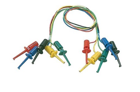
When first using these miniature test leads they worked very well. But after a little time using these leads and problems surfaced. The problem was that they were cheaply made. The connection of the wire and the metal insert probe would break off without much stress placed on them. One or two is understandable, but 5 out of 10 was not the experience I was looking for.
When doing a search for a new product on the Adafruit site I found these test leads

These leads are a little larger than the Jameco test leads, but still were small enough for my use. Construction and connections were of high quality and work perfectly and held up with repeated use. So these are my new go to test leads for my development efforts. They will be seen in a number of up coming Instructables that I am working on and all my testing of sensors and connectors.
WATER LEVEL INDICATOR – AQUAPONICS quest for a useful one September 13, 2018
Posted by rik94566 in adafruit, aquaponic automation, aquaponics, Balcony Garden, DIY aquaponics, Instructables, internet of farming, IoT aquaponics, rik kretzinger, rik94566, sensor, Uncategorized.Tags: aquaponics, DIY aquaponics, rik, ultrasonic sensor
2 comments
THE PROBLEM IN AQUAPONICS for me —
Up to this point I have wanted to have a simple, but effective water level indicator sensor for the water level in the Balcony Garden fish tank component of the build – that works!
Aquaponic Sensor Set for Balcony Garden — see section on ultrasonic sensor
I spent a lot of time working with and trying to stabilize a ultrasonic solution.
First off these sensors are not waterproof ( the waterproof version is around $85.00 US Waterproof version). The non-waterproof versions run around $5.00 US. So this would seem the best way to go and work to make it work by using some waterproofing strategies. Hard to do when working in an aquaponic environment.
Next they are very hard to mount in a way that they can be useful to determining water level in a tank. There are a lot of instructables talking about this aspect for these sensors and even more youtube articles, but most if not all are just demos and breadboard applications. No real useful solutions that really can be implemented in a scalable way.
Final issue is that I have yet to be able to stabilize these sensors and have wasted a lot of time trying to get them to be reliable in a usable way.
SOLUTION – find a better method or be able to purchase one that actually gets the job done in a simple and affordable and scalable way.

Arduino IDE running on RPi using 5″ HDMI 800 X 480 display March 30, 2017
Posted by rik94566 in 800 X 480 display, adafruit, agponics.com, arduino, DIY aquaponics, Instructables, IoT aquaponics, Raspberry PI, rik kretzinger, rik94566, Uncategorized.Tags: 800X480 display, arduino, arduino IDE, rik, rik94566
add a comment
Since the problem with using a 5″ HDMI display was worked with the Raspberry Pi. A new problem developed that needed to be addressed. Running Arduino IDE on Raspberry Pi using the 5″ HDMI display at 800 X 480 resolution. The problem is that the Arduino IDE bleeds off the edges of the display (see picture below). The issue is that the Arduino IDE cannot be moved around to get access to the menu options. So there is no way to check libraries or setting to insure sketches are being up-loaded correctly. No new sketches can be opened either. Major pain.
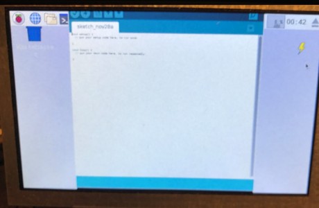
After some research and a little time solving the Raspberry Pi – Jessie with Pixel display issue I found a solution that resolves this issue as well.
I wrote an Instructable to document what is needed, so check it out if this is a issue for you.
Window size issue with Arduino IDE and RPi
Here are the results:

800 X 480 – 5″ HDMI display – Jessie with Pixel – resolution issue – Raspberry Pi March 16, 2017
Posted by rik94566 in 800 X 480 display, adafruit, aquaponic automation, aquaponics electronics, Balcony Garden, DIY aquaponics, Electronic Componets, indoor aquaponics, Instructables, IoT aquaponics, Raspberry PI, rik kretzinger, rik94566.add a comment

This display was purchased to allow a graphical interface element to the automation effort of aquaponic systems. So I was very happy to find this display and it could easily be integrated into the overall design with a very small footprint.
ADAFRUIT is quite clear that that this 5″ HDMI display will not work without changes to the “config.txt” file to set-up for the different display size. In this case 800 X 480 resolution. The documentation to make these changes is very good and works as documented.
THAT IS UNTIL A NEW RELEASE OF RASPBERRY PI OS —
As always technology never stands still. Advances are made almost daily when it comes to Raspberry Pi and the OS is no exception. In late 2016 a new upgrade was rolled out called “JESSIE” with Pixel. There was a lot of buzz about this new upgrade and it does look and perform much better over all. Once you upgrade or update there is no going back.
The problem with the “JESSIE” upgrade is that now the solution provide by ADAFRUIT for the 5″ HDMI display no longer worked very well and was unusable as a display on the Balcony Gardens.
A fix was needed, but since “JESSIE” was so new no one was really aware of this resolution issue and the resolution issue was not even being talked about on ADAFRUIT site or in the Raspberry Pi forums.
After a lot of searching and months later a solution was found.
Long story so I will not go into details of the issue, but have documented it all in an Instructable that can be found here:
Instructable – 800 X 480 5″ HDMI display – resolution issue
HERE IS THE FIX AND LINK TO THE SOLUTION:
Actual changes needed in the “config.txt” file for use:
In the file /boot/config.txt add the following text to the end of the file:
#increase HDMI signal strength
config_hdmi_boost=4
#remove black borders
disable_overscan=1
#set specific CVT mode
hdmi_cvt 800 480 60 6 0 0 0
#set CVT as default
hdmi_group=2
hdmi_mode=87
dtoverlay=ads7846,cs=1,penirq=25,penirq_pull=2,speed=50000,keep_vref
_on=0,swapxy=0,pmax=255,xohms=150,xmin=200,xmax=3900,
ymin=200,ymax=3900
dtoverlay=w1-gpio-pullup,gpiopin=4,extpullup=1
Save the config file and then do this: (see note below about this one)
sudo apt -get install xinput-calibrator
I have not tried using the above install command, because I was able to gain the results I needed without it. I believe like Auvy that sometimes less is more!
HERE IS THE LINK TO THE SOLUTION AS SHOWN ABOVE:
AMAZON SOLUTION – 5″ HDMI display – JESSIE – Pixel – resolution issue
TOWER SYSTEM – set-up at Maker Faire 2014 May 22, 2014
Posted by rik94566 in adafruit, agponics.com, arduino, DIY aquaponics, DS18B20, Electronic Componets, indoor aquaponics, indoor gardens, indoor growing, Internet-of-Farming, IoT aquaponics, One-wire, Raspberry PI, Tower System, Tower Tubes.Tags: agponics, aquaponics, automation, Controlled Environment Agriculture, DIY aquaponics, indoor aquaponics, IoT, Maker Faire, microcontroller, rik kretzinger, sensor
2 comments
IT’S OFFICIAL – Maker Faire 2014 – we will be there with a booth to show case Tower unit March 24, 2014
Posted by rik94566 in adafruit, agponic MD, agponicMD, agponics.com, aquaponic automation, aquaponics, aquaponics electronics, arduino, DIY aquaponics, DS18B20, indoor aquaponics, Internet-of-Farming, IoT aquaponics, One-wire, PRODUCTS, sensor, Stainless Steel Temp Probe, Tower Pocket Block, Tower Tubes, Yourduino.Tags: aquaponic automation, arduino sketch, DIY aquaponics, indoor aquaponics, microcontroller, rik kretzinger
4 comments
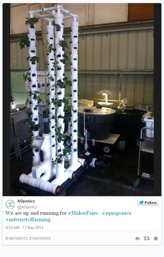
IT’S OFFICIAL NOW:
I’ve been accepted to exhibit at @MakerFaire Bay Area on May 17 & 18, 2014 http://makerfaire.com/
#20475 – internet of farming arduino-based aquaponics
Will be able to show case a number of new leading edge things that I have been developing.
Here are just a few of them:
Design of a “Radial Flow Filter” for the tower unit system ( will be blogging and doing a Youtube video about it shortly”
Venturi DIY design that will replace air pumps on my systems.
Aquaponic Fog Unit that I have just completed and in testing mode now.
Have fully working Tower unit with totally enabled IoT features that show case the latest developments in this technology as related to aquaponics.

New Product — DS18B20 — High Heat & Waterproof January 21, 2012
Posted by rik94566 in 1-wire, adafruit, aquaponic automation, aquaponics, arduino, DIY aquaponics, DS18B20, One-wire, sensor, Stainless Steel Temp Probe, Temperature Probe.Tags: 1-wire, aquaponic automation, arduino, automation, DIY aquaponics, DS18B20, microcontroller, rik kretzinger, sensor, Temperature Probe
4 comments

NEW PRODUCT – High Temp Waterproof DS18B20 Digital temperature sensor + extras. This is a pre-wired and waterproofed version of the DS18B20 sensor made with a PTFE wire cable. Handy for when you need to measure something far away, or in wet conditions. This sensor is a little more expensive than the other waterproof version we have with a PVC cable because this one can be used up to 125°C – the limit of the sensor itself.
Because the sensor signal is digital, you don’t get any signal degradation even over long distances! These 1-wire digital temperature sensors are fairly precise (±0.5°C over much of the range) and can give up to 12 bits of precision from the onboard digital-to-analog converter. They work great with any microcontroller using a single digital pin, and you can even connect multiple ones to the same pin, each one has a unique 64-bit ID burned in at the factory to differentiate them. Usable with 3.0-5.0V systems.
The only downside is they use the Dallas 1-Wire protocol, which is somewhat complex, and requires a bunch of code to parse out the communication. If you want something really simple, and you have an analog input pin, the TMP36 is trivial to get going.
We toss in a 4.7k resistor, which is required as a pullup from the DATA to VCC line when using the sensor. We don’t have a detailed tutorial up yet but you can get started by using the Dallas Temperature Control Arduino library which requires also the OneWire Library.
Cable specs:
- Stainless steel #306 tube 6mm diameter by 40mm long
- Cable is 5 ft long / 150cm long
- Contains DS18B20 temperature sensor
- Three wires – Brown connects to 3-5V, Black connects to ground and Blue is data.
DS18B20 Technical specs:
- Usable temperature range: -55 to 125°C (-67°F to +257°F)
- 9 to 12 bit selectable resolution
- Uses 1-Wire interface- requires only one digital pin for communication
- Unique 64 bit ID burned into chip
- Multiple sensors can share one pin
- ±0.5°C Accuracy from -10°C to +85°C
- Temperature-limit alarm system
