Technology is complicated — May 8, 2015
Posted by rik94566 in Controlled Environment Agriculture, DIY aquaponics, Electronic Componets, indoor aquaponics, IoT aquaponics, Temperature Probe.Tags: agponics, aquaponic automation, aquaponics, arduino, arduino sketch, automation, DIY aquaponics, indoors aquaponics, microcontroller, rik kretzinger, Temboo, YUN
add a comment
I say this because I will be displaying my aquaponic – IoT – Balcony Unit at Maker Faire next week in San Mateo. To accomplish the IoT part of the build I have to use technology that allows for internet communication thus IoT! Well there are many options available to accomplish this task – some not so easy and others not enough features to be effective for this project.
So my choice in this case is the Arduino YUN —

I made this choice because I had one (but had not used it as yet) and the fact that documentation on it is easy to find. The other fact is that Temboo www.temboo.com uses the YUN as one of its options for their solution to the Internet of Things and I am working with them on this open source project so many others will be able to get up and running in short order and have simpler options to add additional capability based on the persons needs and I will not have to supply the customer support for any aspect of the code other than give everyone a stating point.
WELL – that is where things got interesting.
Had to work through getting the YUN on the network of choice. Not a big deal but it took some time and many attempts to get it dialed in because the Arduino instructions tell you to go to arduino.local to find the individual unit. Well this only works about 60% of the time. So the solution is to use the IP address of 192.168.24.1 now I could configure the thing to my liking. Once configured it would not show up in the Arduino IDE at all. Major issue for me as I had no idea if the unit configured or not. I finally when on to my wireless router to see if the board was being recognized. Had to dig out all the USER ID and PASSWORD info and then work through all the menus to determine what in fact was connected to the router. There is was — YEA
Now I had to research out why it was not listed as a port option in my Arduino IDE. Well after some time and deep research I found that Arduino IDE only works some times for the YUN on wireless. So the uploading from Arudino IDE to the board is not an option as most of the YouTube videos demonstrate quite well. This becomes an issue because I found out that as configured the YUN does not have enough on board memory, so a SD card is needed.
Using an SD card with the YUN requires that the card be format using the YUN. To do that you need to know that the YUN is connected to the internet and working properly which is very hard to know if it is or not.
So once you know the YUN is connected and you have it connected through cable to your computer you need a file called ” YunDiskSpaceExpander” found on the Arduino site. Once uploaded you access it through the Serial Monitor of the Arduino IDE. If all goes well you answer a bunch of cryptic questions and bingo the thing kicks off. Once do you have a formated YUN SD enabled board.
Now I am ready for the real fun stuff to generate code to be used through Temboo so I will have “Streaming Data” and text messaging in short order – lets hope!
The good news in all of this is that I will be documenting all of this for the instructions to the Balcony unit for all to use and save anyone interested in building one or gets a kit from me that will be up and running in short order.
See you all at Maker Faire next Saturday if you make it there!
IT’S OFFICIAL – Maker Faire 2014 – we will be there with a booth to show case Tower unit March 24, 2014
Posted by rik94566 in adafruit, agponic MD, agponicMD, agponics.com, aquaponic automation, aquaponics, aquaponics electronics, arduino, DIY aquaponics, DS18B20, indoor aquaponics, Internet-of-Farming, IoT aquaponics, One-wire, PRODUCTS, sensor, Stainless Steel Temp Probe, Tower Pocket Block, Tower Tubes, Yourduino.Tags: aquaponic automation, arduino sketch, DIY aquaponics, indoor aquaponics, microcontroller, rik kretzinger
4 comments
IT’S OFFICIAL NOW:
I’ve been accepted to exhibit at @MakerFaire Bay Area on May 17 & 18, 2014 http://makerfaire.com/
#20475 – internet of farming arduino-based aquaponics
Will be able to show case a number of new leading edge things that I have been developing.
Here are just a few of them:
Design of a “Radial Flow Filter” for the tower unit system ( will be blogging and doing a Youtube video about it shortly”
Venturi DIY design that will replace air pumps on my systems.
Aquaponic Fog Unit that I have just completed and in testing mode now.
Have fully working Tower unit with totally enabled IoT features that show case the latest developments in this technology as related to aquaponics.

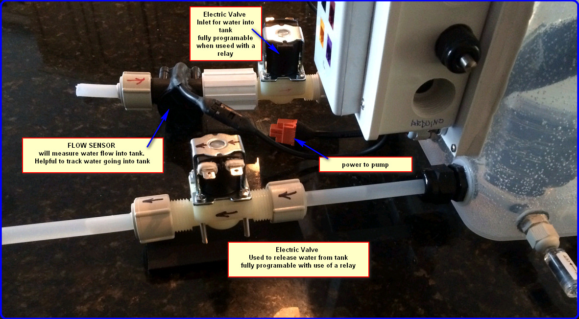
Backside equipment found on agponic-MD unit February 2, 2014
Posted by rik94566 in agponic MD, agponicMD, aquaponic automation, aquaponics, arduino, DIY aquaponics, Electronic Componets, Gravity feed valves, plumbing, sensor.Tags: arduino sketch, automation, DIY aquaponics, indoor aquaponics, IoT, rik kretzinger, sensor
3 comments
NASA Standard – good enough for me March 7, 2013
Posted by rik94566 in agponics.com, DIY aquaponics, indoor aquaponics, Rj45 connector, Standards, Uncategorized.Tags: aquaponic automation, aquaponics, arduino sketch, DIY aquaponics, rik kretzinger
add a comment
I was reading through my blog feeds and ran on to this item:

HERE IS THE LINK IF INTRESTED:
http://blog.makezine.com/2012/02/28/how-to-splice-wire-to-nasa-standards/
I have been interested in establishing standards in all the things that I work on because when I start to scale I will need to have documented processes in place that will allow for building SOP (Standard Operation Procedures). An aquaponics business is no different than other well established industries. So now I have one for all my wire connections that are well documented and well established.
DS18B20 — external power – 5 Probes working April 6, 2012
Posted by rik94566 in 1-wire, aquaponic automation, arduino, DS18B20, One-wire, sensor, Stainless Steel Temp Probe.Tags: 1-wire, aquaponic automation, arduino sketch, automation, DIY aquaponics, DS18B20, rik kretzinger, sensor, Temp Probe
4 comments
Once I got the ground problem worked out and was reading one probe adding 4 more was no sweat…….

5 probe configuration
Here is the sketch I used: ( you will need to change out the HEX code parts for your specific DS18B20)
// This Arduino sketch reads DS18B20 “1-Wire” digital
// temperature sensors.
// Tutorial:
// http://www.hacktronics.com/Tutorials/arduino-1-wire-tutorial.html
//Changed sketch to handle individual temperature probes for testing out software and hub
//each probe is plugged into a wiring harness using either a 4.7K or 2.2K resistor configuration.
//will use this to test power soruce and resistor needed to read 5 temp probes.
//ver-1.01-R
// Rik Kretzinger
// 08/17/2011
#include <OneWire.h>
#include <DallasTemperature.h>
// Data wire is plugged into pin 3 on the Arduino
#define ONE_WIRE_BUS 8
// Setup a oneWire instance to communicate with any OneWire devices
OneWire oneWire(ONE_WIRE_BUS);
// Pass our oneWire reference to Dallas Temperature.
DallasTemperature sensors(&oneWire);
// Assign the addresses of your 1-Wire temp sensors.
// See the tutorial on how to obtain these addresses:
// http://www.hacktronics.com/Tutorials/arduino-1-wire-address-finder.html
DeviceAddress Probe012 = { 0x28, 0xD8, 0x79, 0x31, 0x03, 0x00, 0x00, 0xC6 };
DeviceAddress Probe013 = { 0x28, 0x43, 0x77, 0x22, 0x03, 0x00, 0x00, 0x9D };
DeviceAddress Probe014 = { 0x28, 0x30, 0x65, 0x31, 0x03, 0x00, 0x00, 0x13 };
DeviceAddress Probe015 = { 0x28, 0xDE, 0x9D, 0x31, 0x03, 0x00, 0x00, 0xB1 };
DeviceAddress Probe016 = { 0x28, 0x7E, 0x8A, 0x31, 0x03, 0x00, 0x00, 0xC0 };
void setup(void)
{
// start serial port
Serial.begin(9600);
// Start up the library
sensors.begin();
// set the resolution to 10 bit (good enough?)
sensors.setResolution(Probe012, 10);
sensors.setResolution(Probe013, 10);
sensors.setResolution(Probe014, 10);
sensors.setResolution(Probe015, 10);
sensors.setResolution(Probe016, 10);
}
void printTemperature(DeviceAddress deviceAddress)
{
float tempC = sensors.getTempC(deviceAddress);
if (tempC == -127.00) {
Serial.print(“Error getting temperature”);
} else {
Serial.print(“C: “);
Serial.print(tempC);
Serial.print(” F: “);
Serial.print(DallasTemperature::toFahrenheit(tempC));
}
}
void loop(void)
{
delay(2000);
Serial.println();
Serial.println();
Serial.print(“Getting temperatures…\n\r”);
sensors.requestTemperatures();
Serial.print(“Probe 012 temperature is: “);
printTemperature(Probe012);
Serial.print(“\n\r”);
Serial.print(“Probe 013 temperature is: “);
printTemperature(Probe013);
Serial.print(“\n\r”);
Serial.print(“Probe 014 temperature is: “);
printTemperature(Probe014);
Serial.print(“\n\r”);
Serial.print(“Probe 015 temperature is: “);
printTemperature(Probe015);
Serial.print(“\n\r”);
Serial.print(“Probe 016 temperature is: “);
printTemperature(Probe016);
Serial.print(“\n\r”);
}
DS18B20 — external power supply December 15, 2011
Posted by rik94566 in 1-wire, aquaponic automation, aquaponics, arduino, CEA, Controlled Environment Agriculture, DIY aquaponics, DS18B20, HEX code, indoor aquaponics, indoor gardens, indoor growing, One-wire, probe index, sensor, Sensor Hub, Stainless Steel Temp Probe, Temperature Probe.Tags: 1-wire, aquaponic automation, aquaponic crop, arduino, arduino sketch, automation, CEA, Controlled Environment Agriculture, DIY aquaponics, DS18B20, electronics, indoor aquaponics, indoors aquaponics, microcontroller, rik kretzinger, sensor, Temp Probe, Temperature Probe
1 comment so far
Before I can connect everything up and work with my DS18B20 probes using external power supply I need to get one. The one that I have selected is this one:

5V power supply
DS18B20 – on to external power December 7, 2011
Posted by rik94566 in 1-wire, aquaponic automation, aquaponics, arduino, CEA, Controlled Environment Agriculture, DIY aquaponics, DS18B20, HEX code, indoor aquaponics, indoor gardens, indoor growing, One-wire, probe index, sensor, Sensor Hub, Stainless Steel Temp Probe, Temperature Probe.Tags: 1-wire, aquaponic automation, aquaponic crop, aquaponics, arduino, arduino sketch, automation, CEA, Controlled Environment Agriculture, DIY aquaponics, DS18B20, ds18b20 water proof, electronics, indoor aquaponics, microcontroller, rik kretzinger, sensor, Temp Probe, Temperature Probe, water proof temp probe
2 comments

When you want to learn something new in electronics, you have to start at the bottom. In my mind a circuit layout like this is the bottom for me and it is hard for me to follow. I will be the first to admit that I am not an electrical engineer and don’t want to be one either. I just want a simple way to hook things up and have them work when I need them too. So this layout just gives me a general idea of where to start on hooking up a external power source for my probes. I was at this same point when I started to learn about DS18B20’s and use with an arduino. The good news is that I have a more clear understanding how the DS18B20 functions and how it operates than when I first started on this project.
WHY DO I NEED EXTERNAL POWER FOR MY DS18B20’S ——-
Well that is a very good questions. In most applications and small projects you do not need to know anything about this aspect of the DS18B20’s. In my case as I have been working on this blog several questions have been posed as to power drains on arduino’s if you request to many sensors being driven by the unit and you have long runs to your sensors. So I need to do some research as to how to use a external power source. A lot of places on the internet talk about it, but I have yet to find any source that shows a person how to actually make this work. As for the research here is the best I could find. If you know of others please let me know and I will add it to my library and give you credit for it here.
HERE IS THE BIBLE ON THIS SUBJECT —
http://www.arduino.cc/playground/Learning/OneWire
Normal (external supply) mode
With an external supply, three wires are required: the bus wire, ground, and power. The 4.7k pull-up resistor is still required on the bus wire. As the bus is free for data transfer, the microcontroller can continually poll the state of a device doing a conversion. This way, a conversion request can finish as soon as the device reports being done, as opposed to having to wait 750ms in “parasite” power mode.
Note on resistors: For larger networks, you can try something smaller. The ATmega328/168 datasheet indicates starting at 1k6 and a number of users have found smaller to work better on larger networks.
THAT IS ALL THERE IS — in this bible. Not much of a help in my mind.
HERE IS THE OTHER THING I FOUND:
http://sheepdogguides.com/dst9parasitic.htm
Choosing your 1-Wire chip power mode
Many of the chips in the 1-Wire family from Dallas Semiconductor can be powered “parasitically”… that’s Dallas’s (apt) name for the system used.
The advantage of parasitic powering is that it means you can have a two wire MicroLan. (“MicroLan” is just Dallas’s trademarked name for a bunch of 1-Wire chips “playing nicely” with each other and a “master” device, e.g. a PC or simple microcontroller, e.g. Arduino, in charge of the network of 1-Wire sensors, actuators, storage units, etc.) If you don’t use parasitic powering, then you need to run three wires from chip to chip to chip. (An aside: You should be aware that MicroLans don’t like star topographies. If you need a star, you need a hub to split it into separate, non- star, legs.)
I’ve often used parasitic powering entirely successfully. However, if you have a lot of chips on the MicroLan, or high poll rates, the time may come when supplying the chips which can be powered parasitically makes sense. It isn’t difficult… especially if you provided for the possibility that you’d like to make the change when you first set up your MicroLan.
For example…
Just as an example, let’s consider a MicroLan that is reading temperatures in various parts of a large greenhouse.
We’ll assume you’re using chips from the DS182x family, in a TO92 package, the little blob of plastic with three “legs”.
To use those chips parasitically, you just connect two of the legs to one another, and that leaves you with two connections which go to the two wires of the basic MicroLan.
Now… and this is what I meant about giving yourself options for the future… rather than doing that the “obvious” way, using either a small PCB, or simple discrete wires, connect each of the three pins to a separate track or wire, and THEN make your connections to the MicroLan. If later, you want to use non parasitic power, then all you have to do is change a link, or disconnect one of the wires, and you can then supply the chip with its independent V,cc easily, without disturbing what would be fiddly connections to the package’s pins.
Here are the details of which pin is which on the DS1820…

The DS1820’s middle leg goes to the 1-Wire data line.
The DS1820’s leg marked “See text” should be attached to the 5v, or, for parasitic power, connect this pin to ground (zero volts))
And the DS1820’s “1-Wire 0v” should be attached ground,i.e. to zero volts.
(If the above seems over-explained, please remember that this page may be accessed by people who want more than just an idea of what this “parasitic power” thing is all about.)
AND THE LAST ONE I FOUND:
http://forums.parallax.com/showthread.php?135523-ds18b20-sensor-fails-at-high-temperature
- osts
- 117
 Re: ds18b20 sensor fails at high temperature
I may have stumbled on a possible solution, but I am not sure how to code it. The snippet below is from the Maxim data sheet for the ds18b20. If I understand the second paragraph, correctly, I may need to Insert these commands:
Skip rom (cch)
Read power (b4h)
Then initiate a “read time slot”I am not sure how or where to insert these commands in the one wire object.
I am using an external power supply with a 4.7k pullup“The use of parasite power is not recommended for temperatures above +100°C since the DS18B20 may not be able to sustain communications due to the higher leakage currents that can exist at these temperatures. For applications in which such temperatures are likely, it is strongly recommended that the DS18B20 be powered by an external power supply.
In some situations the bus master may not know whether the DS18B20s on the bus are parasite powered or powered by external supplies. The master needs this information to determine if the strong bus pullup should be used during temperature conversions. To get this information, the master can issue a Skip ROM [CCh] command followed by a Read Power Supply [B4h] command followed by a “read time slot”. During the read time slot, parasite powered DS18B20s will pull the bus low, and externally powered DS18B20s will let the bus remain high. If the bus is pulled low, the master knows that it must supply the strong pullup on the 1-Wire bus during temperature conversions.
Not a lot to work with here, but I do have a lay out and now need to assemble the components I will need to pull this off. Don’t you just love electronics and all the neat stuff you get to learn!!!!
DS18B20 — 10 probes – GOING FOR IT November 27, 2011
Posted by rik94566 in 1-wire, aquaponic automation, aquaponics, arduino, CEA, Controlled Environment Agriculture, DIY aquaponics, DS18B20, HEX code, indoor aquaponics, indoor gardens, indoor growing, One-wire, probe index, sensor, Sensor Hub, Stainless Steel Temp Probe, Temperature Probe.Tags: 1-wire, aquaponic automation, aquaponic crop, arduino, arduino sketch, automation, CEA, Controlled Environment Agriculture, DIY aquaponics, DS18B20, electronics, indoor aquaponics, microcontroller, rik kretzinger, sensor, Temp Probe, Temperature Probe
4 comments
Well – I have the components assembled now so it is the time to “GO FOR 10 PROBES’ connected up. I will be using 4.7K ohm resistors with power supplied by my arduino.
HERE IS THE CONFIGURATION:

BUS AND 10 PROBES
HERE IS THE SKETCH USING 10 PROBES:
// This Arduino sketch reads DS18B20 “1-Wire” digital
// temperature sensors.
// Tutorial:
// http://www.hacktronics.com/Tutorials/arduino-1-wire-tutorial.html
//Changed sketch to handle 10 individual temperature probes for testing out software and 2 hub
//configuration – each probe is plugged into a wiring harness using either a 4.7K or 2.2K resistor.
//will use this to test power source and resistor needed to read 10 temp probes.
//ver-1.01-R
// Rik Kretzinger
// 11/26/2011
#include <OneWire.h>
#include <DallasTemperature.h>
// Data wire is plugged into pin 3 on the Arduino
#define ONE_WIRE_BUS 8
// Setup a oneWire instance to communicate with any OneWire devices
OneWire oneWire(ONE_WIRE_BUS);
// Pass our oneWire reference to Dallas Temperature.
DallasTemperature sensors(&oneWire);
// Assign the addresses of your 1-Wire temp sensors.
// See the tutorial on how to obtain these addresses:
// http://www.hacktronics.com/Tutorials/arduino-1-wire-address-finder.html
DeviceAddress Probe007 = { 0x28, 0x34, 0x6F, 0x22, 0x03, 0x00, 0x00, 0xC2 };
DeviceAddress Probe008 = { 0x28, 0x56, 0x52, 0x31, 0x03, 0x00, 0x00, 0xB7 };
DeviceAddress Probe009 = { 0x28, 0x2F, 0x5C, 0x31, 0x03, 0x00, 0x00, 0x1B };
DeviceAddress Probe010 = { 0x28, 0xD4, 0x81, 0x31, 0x03, 0x00, 0x00, 0x23 };
DeviceAddress Probe011 = { 0x28, 0xF4, 0x6B, 0x31, 0x03, 0x00, 0x00, 0xF2 };
DeviceAddress Probe012 = { 0x28, 0xD8, 0x79, 0x31, 0x03, 0x00, 0x00, 0xC6 };
DeviceAddress Probe013 = { 0x28, 0x43, 0x77, 0x22, 0x03, 0x00, 0x00, 0x9D };
DeviceAddress Probe014 = { 0x28, 0x30, 0x65, 0x31, 0x03, 0x00, 0x00, 0x13 };
DeviceAddress Probe015 = { 0x28, 0xDE, 0x9D, 0x31, 0x03, 0x00, 0x00, 0xB1 };
DeviceAddress Probe016 = { 0x28, 0x7E, 0x8A, 0x31, 0x03, 0x00, 0x00, 0xC0 };
void setup(void)
{
// start serial port
Serial.begin(9600);
// Start up the library
sensors.begin();
// set the resolution to 10 bit (good enough?)
sensors.setResolution(Probe007, 10);
sensors.setResolution(Probe008, 10);
sensors.setResolution(Probe009, 10);
sensors.setResolution(Probe010, 10);
sensors.setResolution(Probe011, 10);
sensors.setResolution(Probe012, 10);
sensors.setResolution(Probe013, 10);
sensors.setResolution(Probe014, 10);
sensors.setResolution(Probe015, 10);
sensors.setResolution(Probe016, 10);
}
void printTemperature(DeviceAddress deviceAddress)
{
float tempC = sensors.getTempC(deviceAddress);
if (tempC == -127.00) {
Serial.print(“Error getting temperature”);
} else {
Serial.print(“C: “);
Serial.print(tempC);
Serial.print(” F: “);
Serial.print(DallasTemperature::toFahrenheit(tempC));
}
}
void loop(void)
{
delay(2000);
Serial.println();
Serial.println();
Serial.print(“Getting temperatures…\n\r”);
sensors.requestTemperatures();
Serial.print(“Probe 007 temperature is: “);
printTemperature(Probe007);
Serial.print(“\n\r”);
Serial.print(“Probe 008 temperature is: “);
printTemperature(Probe008);
Serial.print(“\n\r”);
Serial.print(“Probe 009 temperature is: “);
printTemperature(Probe009);
Serial.print(“\n\r”);
Serial.print(“Probe 010 temperature is: “);
printTemperature(Probe010);
Serial.print(“\n\r”);
Serial.print(“Probe 011 temperature is: “);
printTemperature(Probe011);
Serial.print(“\n\r”);
Serial.print(“Probe 012 temperature is: “);
printTemperature(Probe012);
Serial.print(“\n\r”);
Serial.print(“Probe 013 temperature is: “);
printTemperature(Probe013);
Serial.print(“\n\r”);
Serial.print(“Probe 014 temperature is: “);
printTemperature(Probe014);
Serial.print(“\n\r”);
Serial.print(“Probe 015 temperature is: “);
printTemperature(Probe015);
Serial.print(“\n\r”);
Serial.print(“Probe 016 temperature is: “);
printTemperature(Probe016);
Serial.print(“\n\r”);
}
HERE ARE THE RESULTS:
DS18B20 HEX code – 5 probes Hooked-UP November 20, 2011
Posted by rik94566 in 1-wire, aquaponic automation, aquaponics, arduino, CEA, Controlled Environment Agriculture, DIY aquaponics, DS18B20, HEX code, indoor aquaponics, One-wire, probe index, sensor, Sensor Hub, Stainless Steel Temp Probe, Temperature Probe.Tags: 1-wire, aquaponic automation, aquaponic crop, aquaponics, arduino, arduino sketch, automation, CEA, Controlled Environment Agriculture, DIY aquaponics, DS18B20, electronics, indoor aquaponics, microcontroller, rik kretzinger, sensor, Temp Probe, Temperature Probe
2 comments
I am now ready to try 5 probes using HEX code:

5 probes 4.7 resistor
Here is the setup using my 4.7 ohm resistor harness setup. I also build a 5 connector ground setup to make much easier to control the ground connections.
Here is the sketch that I used with the 5 probe configuration. You will need to determine your HEX code for each DA18B20 and replace in the sketch for your situation.
// This Arduino sketch reads DS18B20 “1-Wire” digital
// temperature sensors.
// Tutorial:
// http://www.hacktronics.com/Tutorials/arduino-1-wire-tutorial.html
//Changed sketch to handle individual temperature probes for testing out software and hub
//each probe is plugged into a wiring harness using either a 4.7K or 2.2K resistor configuration.
//will use this to test power soruce and resistor needed to read 5 temp probes.
//ver-1.01-R
// Rik Kretzinger
// 08/17/2011
#include <OneWire.h>
#include <DallasTemperature.h>
// Data wire is plugged into pin 3 on the Arduino
#define ONE_WIRE_BUS 8
// Setup a oneWire instance to communicate with any OneWire devices
OneWire oneWire(ONE_WIRE_BUS);
// Pass our oneWire reference to Dallas Temperature.
DallasTemperature sensors(&oneWire);
// Assign the addresses of your 1-Wire temp sensors.
// See the tutorial on how to obtain these addresses:
// http://www.hacktronics.com/Tutorials/arduino-1-wire-address-finder.html
DeviceAddress Probe007 = { 0x28, 0x34, 0x6F, 0x22, 0x03, 0x00, 0x00, 0xC2 };
DeviceAddress Probe008 = { 0x28, 0x56, 0x52, 0x31, 0x03, 0x00, 0x00, 0xB7 };
DeviceAddress Probe009 = { 0x28, 0x2F, 0x5C, 0x31, 0x03, 0x00, 0x00, 0x1B };
DeviceAddress Probe010 = { 0x28, 0xD4, 0x81, 0x31, 0x03, 0x00, 0x00, 0x23 };
DeviceAddress Probe011 = { 0x28, 0xF4, 0x6B, 0x31, 0x03, 0x00, 0x00, 0xF2 };
void setup(void)
{
// start serial port
Serial.begin(9600);
// Start up the library
sensors.begin();
// set the resolution to 10 bit (good enough?)
sensors.setResolution(Probe007, 10);
sensors.setResolution(Probe008, 10);
sensors.setResolution(Probe009, 10);
sensors.setResolution(Probe010, 10);
sensors.setResolution(Probe011, 10);
}
void printTemperature(DeviceAddress deviceAddress)
{
float tempC = sensors.getTempC(deviceAddress);
if (tempC == -127.00) {
Serial.print(“Error getting temperature”);
} else {
Serial.print(“C: “);
Serial.print(tempC);
Serial.print(” F: “);
Serial.print(DallasTemperature::toFahrenheit(tempC));
}
}
void loop(void)
{
delay(2000);
Serial.print(“Getting temperatures…\n\r”);
sensors.requestTemperatures();
Serial.print(“Probe 007 temperature is: “);
printTemperature(Probe007);
Serial.print(“\n\r”);
Serial.print(“Probe 008 temperature is: “);
printTemperature(Probe008);
Serial.print(“\n\r”);
Serial.print(“Probe 009 temperature is: “);
printTemperature(Probe009);
Serial.print(“\n\r”);
Serial.print(“Probe 010 temperature is: “);
printTemperature(Probe010);
Serial.print(“\n\r”);
Serial.print(“Probe 011 temperature is: “);
printTemperature(Probe011);
Serial.print(“\n\r”);
}
5 PROBES WORKING:
DS18B20 – – 2 temp probe — CORRECTIONS MADE November 16, 2011
Posted by rik94566 in 1-wire, aquaponic automation, aquaponics, arduino, CEA, Controlled Environment Agriculture, DIY aquaponics, DS18B20, HEX code, indoor aquaponics, indoor gardens, One-wire, sensor, Sensor Hub, Stainless Steel Temp Probe, Temperature Probe.Tags: 1-wire, aquaponic automation, aquaponic crop, aquaponics, arduino, arduino sketch, automation, CEA, Controlled Environment Agriculture, DIY aquaponics, DS18B20, indoor aquaponics, microcontroller, rik kretzinger, sensor, Temp Probe, Temperature Probe
add a comment
The corrections to the HEX code have now been made and the sketch works great. Here are the results:
