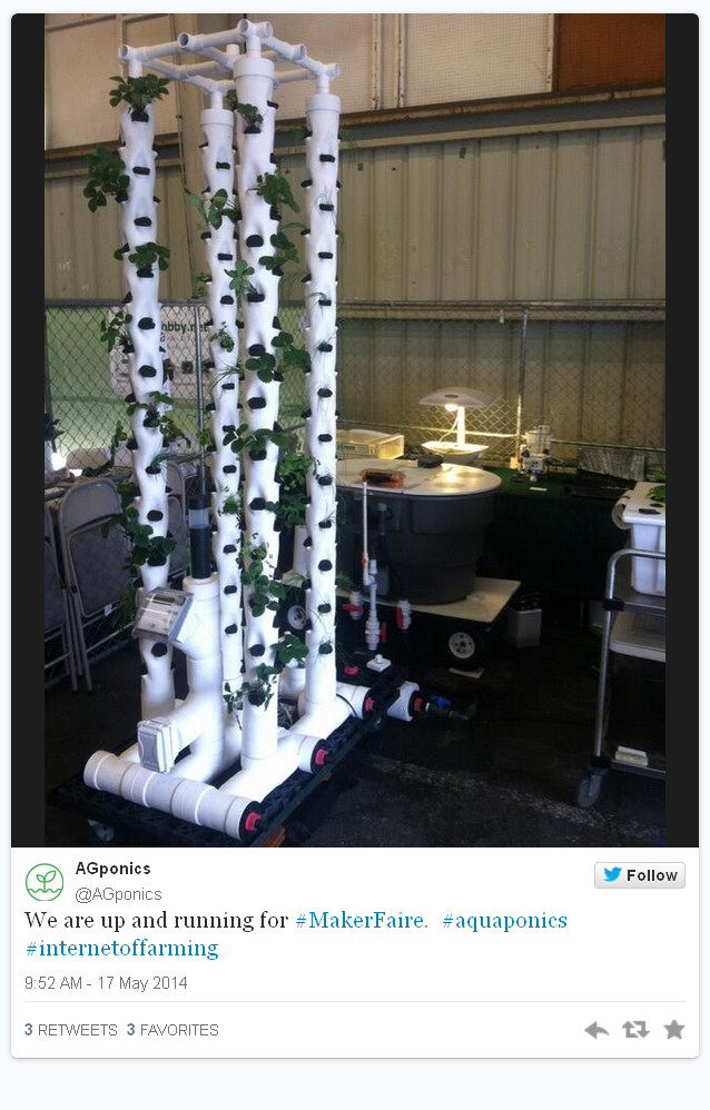
TOWER SYSTEM – set-up at Maker Faire 2014 May 22, 2014
Posted by rik94566 in adafruit, agponics.com, arduino, DIY aquaponics, DS18B20, Electronic Componets, indoor aquaponics, indoor gardens, indoor growing, Internet-of-Farming, IoT aquaponics, One-wire, Raspberry PI, Tower System, Tower Tubes.Tags: agponics, aquaponics, automation, Controlled Environment Agriculture, DIY aquaponics, indoor aquaponics, IoT, Maker Faire, microcontroller, rik kretzinger, sensor
2 comments
EDITOR’S CHOICE – not once – but 3 times @ Maker Faire – WOW May 21, 2014
Posted by rik94566 in agponics.com, aquaponic automation, aquaponics, aquaponics electronics, arduino, DIY aquaponics, indoor aquaponics, indoor gardens, indoor growing, Internet-of-Farming, IoT aquaponics, Raspberry PI, sensor, Tower System.Tags: aquaponic automation, aquaponics, automation, DIY aquaponics, indoor aquaponics, microcontroller, rik kretzinger
2 comments
Very few displays achieve 3 EDITOR CHOICE AWARDS —

INDOOR GARDEN SHOW – SF September 11, 2013
Posted by rik94566 in agponics.com, Air Pots, Crop, DIY aquaponics, indoor gardens, indoor growing, PRODUCTS.Tags: aquaponic automation, automation, Controlled Environment Agriculture, DIY aquaponics, rik kretzinger
add a comment
This past July I was able to attend the Indoor Garden Show in San Francisco.
Have always wanted to attend for the past 3 or 4 years, but was unable due to my personal vacation during the same time.
Well this year it worked out and got to spend a whole day there with a large number of others.
Found some very interesting new items that I will be able to put to work on some up coming projects. I will blog about them as I have time.
The one that was of most interest are Air Pots. This is a product that will have major impact for me going forward. I will be blogging about it and how I am using it in the next few posts. So stay tuned.

DS18B20 — external power supply December 15, 2011
Posted by rik94566 in 1-wire, aquaponic automation, aquaponics, arduino, CEA, Controlled Environment Agriculture, DIY aquaponics, DS18B20, HEX code, indoor aquaponics, indoor gardens, indoor growing, One-wire, probe index, sensor, Sensor Hub, Stainless Steel Temp Probe, Temperature Probe.Tags: 1-wire, aquaponic automation, aquaponic crop, arduino, arduino sketch, automation, CEA, Controlled Environment Agriculture, DIY aquaponics, DS18B20, electronics, indoor aquaponics, indoors aquaponics, microcontroller, rik kretzinger, sensor, Temp Probe, Temperature Probe
1 comment so far
Before I can connect everything up and work with my DS18B20 probes using external power supply I need to get one. The one that I have selected is this one:

5V power supply
DS18B20 – on to external power December 7, 2011
Posted by rik94566 in 1-wire, aquaponic automation, aquaponics, arduino, CEA, Controlled Environment Agriculture, DIY aquaponics, DS18B20, HEX code, indoor aquaponics, indoor gardens, indoor growing, One-wire, probe index, sensor, Sensor Hub, Stainless Steel Temp Probe, Temperature Probe.Tags: 1-wire, aquaponic automation, aquaponic crop, aquaponics, arduino, arduino sketch, automation, CEA, Controlled Environment Agriculture, DIY aquaponics, DS18B20, ds18b20 water proof, electronics, indoor aquaponics, microcontroller, rik kretzinger, sensor, Temp Probe, Temperature Probe, water proof temp probe
2 comments

When you want to learn something new in electronics, you have to start at the bottom. In my mind a circuit layout like this is the bottom for me and it is hard for me to follow. I will be the first to admit that I am not an electrical engineer and don’t want to be one either. I just want a simple way to hook things up and have them work when I need them too. So this layout just gives me a general idea of where to start on hooking up a external power source for my probes. I was at this same point when I started to learn about DS18B20’s and use with an arduino. The good news is that I have a more clear understanding how the DS18B20 functions and how it operates than when I first started on this project.
WHY DO I NEED EXTERNAL POWER FOR MY DS18B20’S ——-
Well that is a very good questions. In most applications and small projects you do not need to know anything about this aspect of the DS18B20’s. In my case as I have been working on this blog several questions have been posed as to power drains on arduino’s if you request to many sensors being driven by the unit and you have long runs to your sensors. So I need to do some research as to how to use a external power source. A lot of places on the internet talk about it, but I have yet to find any source that shows a person how to actually make this work. As for the research here is the best I could find. If you know of others please let me know and I will add it to my library and give you credit for it here.
HERE IS THE BIBLE ON THIS SUBJECT —
http://www.arduino.cc/playground/Learning/OneWire
Normal (external supply) mode
With an external supply, three wires are required: the bus wire, ground, and power. The 4.7k pull-up resistor is still required on the bus wire. As the bus is free for data transfer, the microcontroller can continually poll the state of a device doing a conversion. This way, a conversion request can finish as soon as the device reports being done, as opposed to having to wait 750ms in “parasite” power mode.
Note on resistors: For larger networks, you can try something smaller. The ATmega328/168 datasheet indicates starting at 1k6 and a number of users have found smaller to work better on larger networks.
THAT IS ALL THERE IS — in this bible. Not much of a help in my mind.
HERE IS THE OTHER THING I FOUND:
http://sheepdogguides.com/dst9parasitic.htm
Choosing your 1-Wire chip power mode
Many of the chips in the 1-Wire family from Dallas Semiconductor can be powered “parasitically”… that’s Dallas’s (apt) name for the system used.
The advantage of parasitic powering is that it means you can have a two wire MicroLan. (“MicroLan” is just Dallas’s trademarked name for a bunch of 1-Wire chips “playing nicely” with each other and a “master” device, e.g. a PC or simple microcontroller, e.g. Arduino, in charge of the network of 1-Wire sensors, actuators, storage units, etc.) If you don’t use parasitic powering, then you need to run three wires from chip to chip to chip. (An aside: You should be aware that MicroLans don’t like star topographies. If you need a star, you need a hub to split it into separate, non- star, legs.)
I’ve often used parasitic powering entirely successfully. However, if you have a lot of chips on the MicroLan, or high poll rates, the time may come when supplying the chips which can be powered parasitically makes sense. It isn’t difficult… especially if you provided for the possibility that you’d like to make the change when you first set up your MicroLan.
For example…
Just as an example, let’s consider a MicroLan that is reading temperatures in various parts of a large greenhouse.
We’ll assume you’re using chips from the DS182x family, in a TO92 package, the little blob of plastic with three “legs”.
To use those chips parasitically, you just connect two of the legs to one another, and that leaves you with two connections which go to the two wires of the basic MicroLan.
Now… and this is what I meant about giving yourself options for the future… rather than doing that the “obvious” way, using either a small PCB, or simple discrete wires, connect each of the three pins to a separate track or wire, and THEN make your connections to the MicroLan. If later, you want to use non parasitic power, then all you have to do is change a link, or disconnect one of the wires, and you can then supply the chip with its independent V,cc easily, without disturbing what would be fiddly connections to the package’s pins.
Here are the details of which pin is which on the DS1820…

The DS1820’s middle leg goes to the 1-Wire data line.
The DS1820’s leg marked “See text” should be attached to the 5v, or, for parasitic power, connect this pin to ground (zero volts))
And the DS1820’s “1-Wire 0v” should be attached ground,i.e. to zero volts.
(If the above seems over-explained, please remember that this page may be accessed by people who want more than just an idea of what this “parasitic power” thing is all about.)
AND THE LAST ONE I FOUND:
http://forums.parallax.com/showthread.php?135523-ds18b20-sensor-fails-at-high-temperature
- osts
- 117
 Re: ds18b20 sensor fails at high temperature
I may have stumbled on a possible solution, but I am not sure how to code it. The snippet below is from the Maxim data sheet for the ds18b20. If I understand the second paragraph, correctly, I may need to Insert these commands:
Skip rom (cch)
Read power (b4h)
Then initiate a “read time slot”I am not sure how or where to insert these commands in the one wire object.
I am using an external power supply with a 4.7k pullup“The use of parasite power is not recommended for temperatures above +100°C since the DS18B20 may not be able to sustain communications due to the higher leakage currents that can exist at these temperatures. For applications in which such temperatures are likely, it is strongly recommended that the DS18B20 be powered by an external power supply.
In some situations the bus master may not know whether the DS18B20s on the bus are parasite powered or powered by external supplies. The master needs this information to determine if the strong bus pullup should be used during temperature conversions. To get this information, the master can issue a Skip ROM [CCh] command followed by a Read Power Supply [B4h] command followed by a “read time slot”. During the read time slot, parasite powered DS18B20s will pull the bus low, and externally powered DS18B20s will let the bus remain high. If the bus is pulled low, the master knows that it must supply the strong pullup on the 1-Wire bus during temperature conversions.
Not a lot to work with here, but I do have a lay out and now need to assemble the components I will need to pull this off. Don’t you just love electronics and all the neat stuff you get to learn!!!!
DS18B20 — 10 probes – GOING FOR IT November 27, 2011
Posted by rik94566 in 1-wire, aquaponic automation, aquaponics, arduino, CEA, Controlled Environment Agriculture, DIY aquaponics, DS18B20, HEX code, indoor aquaponics, indoor gardens, indoor growing, One-wire, probe index, sensor, Sensor Hub, Stainless Steel Temp Probe, Temperature Probe.Tags: 1-wire, aquaponic automation, aquaponic crop, arduino, arduino sketch, automation, CEA, Controlled Environment Agriculture, DIY aquaponics, DS18B20, electronics, indoor aquaponics, microcontroller, rik kretzinger, sensor, Temp Probe, Temperature Probe
4 comments
Well – I have the components assembled now so it is the time to “GO FOR 10 PROBES’ connected up. I will be using 4.7K ohm resistors with power supplied by my arduino.
HERE IS THE CONFIGURATION:

BUS AND 10 PROBES
HERE IS THE SKETCH USING 10 PROBES:
// This Arduino sketch reads DS18B20 “1-Wire” digital
// temperature sensors.
// Tutorial:
// http://www.hacktronics.com/Tutorials/arduino-1-wire-tutorial.html
//Changed sketch to handle 10 individual temperature probes for testing out software and 2 hub
//configuration – each probe is plugged into a wiring harness using either a 4.7K or 2.2K resistor.
//will use this to test power source and resistor needed to read 10 temp probes.
//ver-1.01-R
// Rik Kretzinger
// 11/26/2011
#include <OneWire.h>
#include <DallasTemperature.h>
// Data wire is plugged into pin 3 on the Arduino
#define ONE_WIRE_BUS 8
// Setup a oneWire instance to communicate with any OneWire devices
OneWire oneWire(ONE_WIRE_BUS);
// Pass our oneWire reference to Dallas Temperature.
DallasTemperature sensors(&oneWire);
// Assign the addresses of your 1-Wire temp sensors.
// See the tutorial on how to obtain these addresses:
// http://www.hacktronics.com/Tutorials/arduino-1-wire-address-finder.html
DeviceAddress Probe007 = { 0x28, 0x34, 0x6F, 0x22, 0x03, 0x00, 0x00, 0xC2 };
DeviceAddress Probe008 = { 0x28, 0x56, 0x52, 0x31, 0x03, 0x00, 0x00, 0xB7 };
DeviceAddress Probe009 = { 0x28, 0x2F, 0x5C, 0x31, 0x03, 0x00, 0x00, 0x1B };
DeviceAddress Probe010 = { 0x28, 0xD4, 0x81, 0x31, 0x03, 0x00, 0x00, 0x23 };
DeviceAddress Probe011 = { 0x28, 0xF4, 0x6B, 0x31, 0x03, 0x00, 0x00, 0xF2 };
DeviceAddress Probe012 = { 0x28, 0xD8, 0x79, 0x31, 0x03, 0x00, 0x00, 0xC6 };
DeviceAddress Probe013 = { 0x28, 0x43, 0x77, 0x22, 0x03, 0x00, 0x00, 0x9D };
DeviceAddress Probe014 = { 0x28, 0x30, 0x65, 0x31, 0x03, 0x00, 0x00, 0x13 };
DeviceAddress Probe015 = { 0x28, 0xDE, 0x9D, 0x31, 0x03, 0x00, 0x00, 0xB1 };
DeviceAddress Probe016 = { 0x28, 0x7E, 0x8A, 0x31, 0x03, 0x00, 0x00, 0xC0 };
void setup(void)
{
// start serial port
Serial.begin(9600);
// Start up the library
sensors.begin();
// set the resolution to 10 bit (good enough?)
sensors.setResolution(Probe007, 10);
sensors.setResolution(Probe008, 10);
sensors.setResolution(Probe009, 10);
sensors.setResolution(Probe010, 10);
sensors.setResolution(Probe011, 10);
sensors.setResolution(Probe012, 10);
sensors.setResolution(Probe013, 10);
sensors.setResolution(Probe014, 10);
sensors.setResolution(Probe015, 10);
sensors.setResolution(Probe016, 10);
}
void printTemperature(DeviceAddress deviceAddress)
{
float tempC = sensors.getTempC(deviceAddress);
if (tempC == -127.00) {
Serial.print(“Error getting temperature”);
} else {
Serial.print(“C: “);
Serial.print(tempC);
Serial.print(” F: “);
Serial.print(DallasTemperature::toFahrenheit(tempC));
}
}
void loop(void)
{
delay(2000);
Serial.println();
Serial.println();
Serial.print(“Getting temperatures…\n\r”);
sensors.requestTemperatures();
Serial.print(“Probe 007 temperature is: “);
printTemperature(Probe007);
Serial.print(“\n\r”);
Serial.print(“Probe 008 temperature is: “);
printTemperature(Probe008);
Serial.print(“\n\r”);
Serial.print(“Probe 009 temperature is: “);
printTemperature(Probe009);
Serial.print(“\n\r”);
Serial.print(“Probe 010 temperature is: “);
printTemperature(Probe010);
Serial.print(“\n\r”);
Serial.print(“Probe 011 temperature is: “);
printTemperature(Probe011);
Serial.print(“\n\r”);
Serial.print(“Probe 012 temperature is: “);
printTemperature(Probe012);
Serial.print(“\n\r”);
Serial.print(“Probe 013 temperature is: “);
printTemperature(Probe013);
Serial.print(“\n\r”);
Serial.print(“Probe 014 temperature is: “);
printTemperature(Probe014);
Serial.print(“\n\r”);
Serial.print(“Probe 015 temperature is: “);
printTemperature(Probe015);
Serial.print(“\n\r”);
Serial.print(“Probe 016 temperature is: “);
printTemperature(Probe016);
Serial.print(“\n\r”);
}
HERE ARE THE RESULTS:
DS18B20 – – 2 temp probe — CORRECTIONS MADE November 16, 2011
Posted by rik94566 in 1-wire, aquaponic automation, aquaponics, arduino, CEA, Controlled Environment Agriculture, DIY aquaponics, DS18B20, HEX code, indoor aquaponics, indoor gardens, One-wire, sensor, Sensor Hub, Stainless Steel Temp Probe, Temperature Probe.Tags: 1-wire, aquaponic automation, aquaponic crop, aquaponics, arduino, arduino sketch, automation, CEA, Controlled Environment Agriculture, DIY aquaponics, DS18B20, indoor aquaponics, microcontroller, rik kretzinger, sensor, Temp Probe, Temperature Probe
add a comment
The corrections to the HEX code have now been made and the sketch works great. Here are the results:
DS18B20 HEX code — move it to the sketch October 27, 2011
Posted by rik94566 in 1-wire, aquaponic automation, aquaponics, arduino, CEA, Controlled Environment Agriculture, DIY aquaponics, DS18B20, HEX code, indoor aquaponics, indoor gardens, indoor growing, One-wire, probe index, sensor, Sensor Hub, Stainless Steel Temp Probe, Temperature Probe.Tags: 1-wire, aquaponic automation, aquaponics, arduino, arduino sketch, automation, CEA, Controlled Environment Agriculture, DIY aquaponics, DS18B20, electronics, hacks, indoor aquaponics, indoors aquaponics, microcontroller, rik kretzinger, sensor, Temp Probe, Temperature Probe
2 comments
Now that I have the HEX code for each temp probe it is time to move it to the working sketch. I will be pulling the sketch from the one used at the hacktronics site.
http://www.hacktronics.com/Tutorials/arduino-1-wire-tutorial.html
Here is the code I pulled. I will work through it to make the changes I will need to make it fit my application.

Areas to be changed
Here is how I will change the HEX code part of the sketch:
DeviceAddress P-011 = { 0x28, 0xF4, 0x6B, 0x31, 0x03, 0x00, 0x00, 0xF2 };
DeviceAddress P-012 = { 0x28, 0xD8, 0x79, 0x31, 0x03, 0x00, 0x00, 0xC6 };
//DeviceAddress P-0XX = { 0xXX, 0xXX, 0xXX, 0xXX, 0xXX, 0xXX, 0xXX, 0xXX };
I will only start by testing out 2 probes
I will make these changes as well:
// start serial port
Serial.begin(9600);
// Start up the library
sensors.begin();
// set the resolution to 10 bit (good enough?)
sensors.setResolution(P-011, 10);
sensors.setResolution(P-012, 10);
//sensors.setResolution(P-0XX, 10);
and change here also:
Serial.print(“Probe 011 temperature is: “);
printTemperature(P-o11);
Serial.print(“\n\r”);
Serial.print(“Probe 012 temperature is: “);
printTemperature(P-012);
Serial.print(“\n\r”);
// Serial.print(“Probe 0XXtemperature is: “);
//printTemperature(P-0XX);
// Serial.print(“\n\r\n\r”);
}
THE WAY FORWARD — use of HEX code for DS18B20 October 6, 2011
Posted by rik94566 in 1-wire, aquaponic automation, aquaponics, arduino, Arduino Your Environment, Controlled Environment Agriculture, DIY aquaponics, DS18B20, indoor aquaponics, indoor gardens, indoor growing, Links, One-wire, Temperature Probe.Tags: aquaponic automation, aquaponic crop, aquaponics, arduino, arduino sketch, automation, CEA, Controlled Environment Agriculture, DIY aquaponics, DS18B20, electronics, indoor aquaponics, indoors aquaponics, microcontroller, Miles Burton, rik kretzinger, sensor, Temp Probe, Temperature Probe
3 comments
It became clear to me that the path I was on was leading me to a deadend when it comes to using a large number of DS18B20 probes. The sketches I was working with had problems for me. A number of comments and suggestions from readers along with research on my part I have figured out that the use of HEX code is the way to go. This new direction will get me to the end now. This seems to be the most traveled path when it comes to the DS18B20 platform. The best work I can find going this direction comes from two main sites. The first site Hacktronics.com has some very good tutorials on this subject. The second site is a spin off of the Hacktronics site in that the same code is used, but changed to be output to a LCD display (very useful stuff). These two sites will be very useful for me going forward and will enable me to finish-up on the Temp probe side of things and will allow me to move on to the others sensors I have been working with.
The first is:
http://www.hacktronics.com/Tutorials/arduino-1-wire-tutorial.html
Second site:
POWERING the DS18B20 September 18, 2011
Posted by rik94566 in 1-wire, aquaponic automation, aquaponics, arduino, CEA, Controlled Environment Agriculture, DIY aquaponics, DS18B20, indoor aquaponics, indoor gardens, indoor growing, One-wire, sensor, Sensor Hub, Stainless Steel Temp Probe, Temperature Probe.Tags: aquaponic automation, aquaponic crop, aquaponics, arduino, arduino sketch, automation, CEA, Controlled Environment Agriculture, DIY aquaponics, DS18B20, indoor aquaponics, indoors aquaponics, microcontroller, rik kretzinger, sensor, Temp Probe, Temperature Probe
add a comment
http://www.arduino.cc/playground/Learning/OneWire
Powering a DS18x20
The chip can be powered two ways. One (the “parasitic” option) means that only two wires need go to the chip. The other may, in some cases, give more reliable operation (parasitic often works well), as an extra wire carrying the power for the chip is involved. For getting started, especially if your chip is within 20 feet of your Arduino, the parasitic option is probably fine.
Parasite power mode
When operating in parasite power mode, only two wires are required: one data wire, and ground. At the master, a 4.7k pull-up resistor must be connected to the 1-wire bus. When the line is in a “high” state, the device pulls current to charge an internal capacitor.
This current is usually very small, but may go as high as 1.5 mA when doing a temperature conversion or writing EEPROM. When a slave device is performing one these operations, the bus master must keep the bus pulled high to provide power until the operation completes; a delay of 750ms is required for a DS18S20 temperature conversion. The master can’t do anything during this time, like issuing commands to other devices, or polling for the slave’s operation to be completed. To support this, the OneWire library makes it possible to have the bus held high after the data is written.
Normal (external supply) mode
With an external supply, three wires are required: the bus wire, ground, and power. The 4.7k pull-up resistor is still required on the bus wire. As the bus is free for data transfer, the microcontroller can continually poll the state of a device doing a conversion. This way, a conversion request can finish as soon as the device reports being done, as opposed to having to wait 750ms in “parasite” power mode.
Note on resistors: For larger networks, try something smaller. The ATmega328/168 datasheet indicates starting at 1k6 and a number of users have found smaller to work better on larger networks.
