Connector Box on agponic-MD February 2, 2014
Posted by rik94566 in 1-wire, agponic MD, agponicMD, agponics.com, aquaponic automation, aquaponics, aquaponics electronics, arduino, DIY aquaponics, DS18B20, Float Sensor, Float Switch, indoor aquaponics, Internet-of-Farming, IoT aquaponics, One-wire, Rj45 connector, Slide Switch, Stainless Steel Temp Probe, SUGRU.Tags: 1-wire, aquaponic automation, Controlled Environment Agriculture, DIY aquaponics, DS18B20, indoor aquaponics, rik kretzinger, Temp Probe, Temperature Probe
add a comment
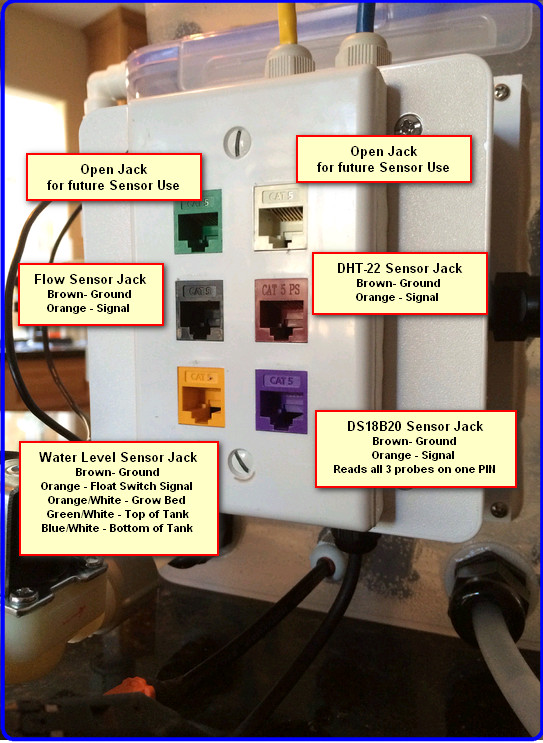
A big part of the aquaponic simulator is the fact that it uses standard RJ-45 jacks to interface with Arduino’s or a Raspberry PI. Having this type setup helps keep all the wires and connectors that are required for the unit to operate in a consistent manor safe and out of possible interaction with water elements.
Here is what is needed to construct this sub-assembly:

When all the above parts come together the finished product looks like this:
Re-Design of agponic-MD January 29, 2014
Posted by rik94566 in agponic MD, agponicMD, agponics.com, aquaponic automation, aquaponics, aquaponics electronics, DS18B20, Float Sensor, Float Switch, indoor aquaponics, IoT aquaponics, One-wire.Tags: aquaponic automation, aquaponics, automation, CAT 5 cable, Controlled Environment Agriculture, DIY aquaponics, indoor aquaponics, microcontroller, rik kretzinger
2 comments
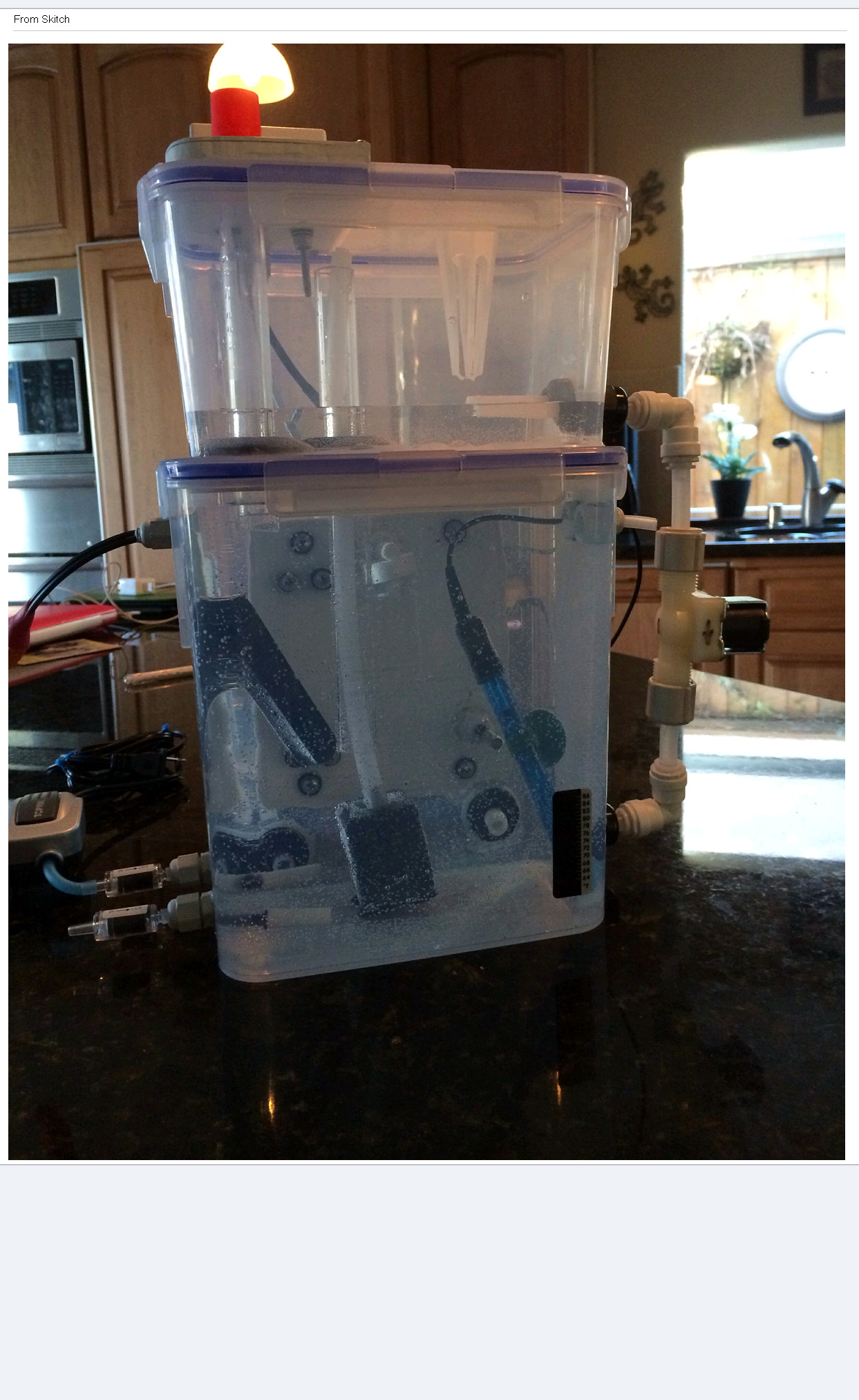 After much thinking about how I could improve the desktop aquaponic automation simulator called agponic-MD (micro-device) I built a new one. It helps to have people that wanted to purchase a few of them. So I got busy and made it a bit larger with expansion capability for future components like a 12V backup system and additional sensors to learn how to automate. Here is the feature set for the re-designed agponic-MD.
Fully valved for water movement and control
Large grow bed and tank configuration
4 – water level control sensors
1 – RH and temp internal probe
3 – temp probes (grow bed / water tank / outside)
1 – water flow sensor
1 – pH probe and connectors
1 – DO or additional probe expansion options for future growth of unit
1 – controllable drain port
1 – grow bed media package to fit grow bed (comes from an established grow bed – so bacteria included)
1 – Container of starter water from an active system ( should you like to cycle the system)
1 – outside tank temp indicator
1 – Heater for tank water
1 – Air pump and stone
Over flow configuration to prevent spillage in grow bed

10,000 views surpassed on Instructables June 11, 2011
Posted by rik94566 in aquaponic automation, aquaponics, arduino, CAT 5 Cable, Crop, DIY aquaponics, DS18B20, Float Sensor, Float Switch, general, Glow Panel 45, Gravity feed valves, Hacks, indoor aquaponics, indoor gardens, indoor growing, Instructables, LED growing, LED lights, plumbing, POW-Rduino, Rj45 connector, sensor, Sensor Hub, Stainless Steel Temp Probe, Standards, sunshine systems, Suppliers, Temperature Probe, Yield Results.Tags: aquaponic automation, aquaponics, arduino, arduino sketch, CAT 5 cable, DIY aquaponics, DS18B20, electronics, float sensor, hacks, indoor aquaponics, indoors aquaponics, microcontroller, rik kretzinger, sensor, Temp Probe, Temperature Probe
1 comment so far
I have written 3 instructables over the last 2 years. I have just gone over 10,000 views. Never thought I would every have had that many views with only 3 instructions. Always good to know people are interested in what I am interested in.

Passed 10,000 views
SUGRU – fills in the holes June 7, 2011
Posted by rik94566 in aquaponic automation, aquaponics, CAT 5 Cable, DIY aquaponics, DS18B20, Float Sensor, Float Switch, Hacks, Home Depot, indoor aquaponics, indoor gardens, indoor growing, Rj45 connector, sensor, Sensor Hub, Stainless Steel Temp Probe, Standards, SUGRU, Suppliers, Temperature Probe.Tags: aquaponic automation, aquaponics, arduino, automation, CAT 5 cable, DIY aquaponics, DS18B20, electronics, float sensor, float switch, hacks, indoor aquaponics, indoors aquaponics, microcontroller, rik kretzinger, sensor, Temp Probe, Temperature Probe
1 comment so far
Now that I have working Sensors on a standardized connection platform (CAT 5 & RJ45). I need to figure out how to use off the shelf housings that will be plug-n-play for my aquaponic units. The problem is that nothing is water resistant and they all have lots of openings. That is because most if not all are for indoor use. All the outdoor options are to large for my applications. So I went with a standard indoor 2-Port QuickPort I purchased at Home Depot.

Leviton 2-Port Surface Mount Housing
With a little help from SUGRU I was able to fill in the holes and can now mount the completed unit on my aquatubes. This will allow me to cover all my sensor connections and transition over to RJ45 connectors.
Here is what I started with:

Starting Housing
Here is what it looked like before assembly:

Openings filled before assembly - Inside look

Bottom View
Here is the completed assembly:

Back View of Completed Assembly

Front View of Completed Assembly
How the openings match-up:

Opening that match-up
Now I am ready to connect up the sensors and mount the completed assembly on the aquatubes hook-up my CAT 5 and I am ready to sense all inputs. O yes, I need some White SUGRU to make it look better. I am placing my order today!
Float Sensor – where do the wires go June 8, 2010
Posted by rik94566 in aquaponics, arduino, Float Sensor.Tags: aquaponics, arduino, automation, float sensor, rik kretzinger
2 comments
Out of the box the float sensor comes with only 2 wires out the bottom. My thoughts are that I need 3 wires to get the thing to work correctly. Not only does the sensor only have 2 wires, but they are both black. Most sensors I have ordered or used in the past have always had a red and black wire to work with. Such is electronics, never what you think it should be. Not much documentation to help figure this wire situation out either. I do know from the Instructable by Luke Iseman for the Garduino his sensors only use 2 wires. Luke was also featured in Make: magazine’s ReMake America volume 18.
Here is the link to this great project:
http://www.instructables.com/id/Garduino-Gardening-Arduino/
If you look at step 4 this is where he does work with the media probe that he constructed. You can look at the electrical drawing and figure it out. I always have a hard time with these as I am new to electronics. My background is horticulture not electronics. I can read enough to see that he uses a 10K ohm resistor (1/4 watt will be fine) between ground (BLACK) and the signal (YELLOW) wire. Good enough for me. So I will work that into my working model. You can get the resistor at Radio Shack for .99 cents.
http://www.radioshack.com/product/index.jsp?productId=2062347
Here is how I wired up the float sensor to the terminal block on the base unit.

Sensor wires to Terminal Block
Not knowing which black wire to use for which screw set, I just put them in the way I wanted and tested the results. Then I switched them and tested again. I could not tell any difference either way. So any way you do it is right. Knowing I needed the 10K resistor I put that in the location shown above. This is IMPORTANT to get right. I connected one end of the resistor in the bottom terminal connector and then ran it to the middle terminal connector. I then took one of the Black wires from the float sensor and placed it in the middle terminal connector. The final connection was to place the unconnected Black wire from the float sensor to the upper terminal connector. Then I was done with this task. In the picture you can see that the bottom terminal connector only has a resistor in the connection. That is because the other side will be where the Arduino ground wire will be placed (BLACK wire). You can place either end of the resistor where you want them. It does not matter as resistors restrict the flow of electrons both ways. Make sure all screw connections are tight or the wires will fall out and you will be doing this again.

Real application configuration
Terminal blocks are not used in aquaponic tanks or grow beds. So we need to see what this will look like in real situations. The full directions on the connections are below.
First connect a resistor to the BLACK wire (GND), next connect the YELLOW wire (COM) to either of the Float Sensor black wires, now connect the other Float Sensor black wire to the RED wire (VCC). Next take the un-connected resistor end and connect to the YELLOW wire & black Float Sensor wire. You are now wired up and ready to go.
To make this water tight you will need to use heat shrink tubing over the connections. If you do not know how to do that ask a friend or check the internet. You can get heat shrink tubing at Radio Shack also. It is also a good idea to solder all the connections. I will be doing an Instructable about how to get the float sensor working and will put a step in to cover the heat shrink thing for everyone. Right now not important.

Connection to Arduino from Terminal Block
I am using a ScrewShield to demonstrate the connections better for you. You can just stick the wire ends in to the correct pins and it will work just fine. Make sure the wires are stripped of insulation before inserting them into the pins or terminal connectors.
Connect BLACK wire into the GND pin. Connect the RED wire into the 5V pin. Next connect YELLOW wire into the Analog 0 (zero) pin. You are now wired up and ready to work with the sensor.
When completed the connections will look like the picture below:

Completed Connections
Getting Ready to test FLOAT SENSOR June 6, 2010
Posted by rik94566 in aquaponics, Float Sensor, sensor.Tags: aquaponics, arduino, float sensor, rik kretzinger, sensor
add a comment
In order to learn how this float sensor works some advance work needed to be done. I needed a container to hold the actual unit that was water tight and allowed for the container to be drained.

This build will allow for testing of a number of situations and help me gain a full understanding of how to use this sensor in aquaponic situations.
Next I needed to finish the build by adding a method to read the sensor and drain water from the container. So I added the following features to the float container. I will cover more on how the wiring works and what is needed to get a reading off the sensor soon.

Components for testing Float Sensor
Looking into the container you can see the drain hole, float and how they are positioned.

Float and Drain positioned inside container
