Connector Box on agponic-MD February 2, 2014
Posted by rik94566 in 1-wire, agponic MD, agponicMD, agponics.com, aquaponic automation, aquaponics, aquaponics electronics, arduino, DIY aquaponics, DS18B20, Float Sensor, Float Switch, indoor aquaponics, Internet-of-Farming, IoT aquaponics, One-wire, Rj45 connector, Slide Switch, Stainless Steel Temp Probe, SUGRU.Tags: 1-wire, aquaponic automation, Controlled Environment Agriculture, DIY aquaponics, DS18B20, indoor aquaponics, rik kretzinger, Temp Probe, Temperature Probe
add a comment
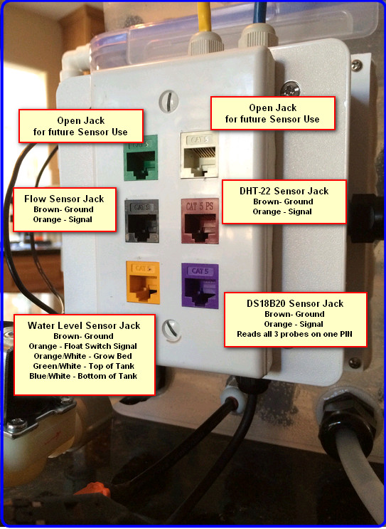
A big part of the aquaponic simulator is the fact that it uses standard RJ-45 jacks to interface with Arduino’s or a Raspberry PI. Having this type setup helps keep all the wires and connectors that are required for the unit to operate in a consistent manor safe and out of possible interaction with water elements.
Here is what is needed to construct this sub-assembly:

When all the above parts come together the finished product looks like this:
TOWER INTERFACE PLATE — protects the dry core of the tower base September 25, 2013
Posted by rik94566 in agponics.com, aquaponics, DIY aquaponics, DS18B20, Hacks, Interface Plate, One-wire, Sensor Hub, Tower System.Tags: 1-wire, aquaponic automation, DIY aquaponics, DS18B20, microcontroller, rik kretzinger
add a comment
Here is the “INTERFACE PLATE” — this plate is inserted into the base of the towers and is sealed. With this interface plate in place wires can be run to tower sensors and power supplied to the pumps that feed the towers. Without these interface plates it would be dangerous to provide power to pumps or connect or disconnect the tower columns.

SUGRU — makes a harness possible August 21, 2011
Posted by rik94566 in aquaponic automation, aquaponics, arduino, CAT 5 Cable, CEA, DIY aquaponics, DS18B20, Hacks, indoor aquaponics, indoor gardens, indoor growing, Rj45 connector, sensor, Sensor Hub, Stainless Steel Temp Probe, Standards, SUGRU, Temperature Probe.Tags: aquaponic automation, aquaponics, arduino, arduino sketch, automation, CAT 5 cable, CEA, Controlled Environment Agriculture, DIY aquaponics, DS18B20, electronics, hacks, indoor aquaponics, microcontroller, rik kretzinger, sensor, sugru, Temp Probe, Temperature Probe
add a comment
In order to connect up 5 DS18B20 temp probes and make sure all the wires and connectors work correctly took some effort. The fact that a pull-up resistor is required to take readings was an issue for me. I have been using 1/4 watt resistors and in tight spaces my resistor wires kept breaking off. So I needed a way to connect it all up and be protected. Sugru saved the day.

Sugru made a strong bond
I showed you the end product as that is what most people are interested in. But it is important to understand how the end product was created.
Here is the starting point:

pull-up resistor configuration
Spacing of the wires and resistor is a big issue here, as if the spacing is off the connectors will not fit into the holders correctly.

one connection made
Next trick was to get 5 connections completed.

5 connections made

bend it just right to get correct spacing

side view

Front view

end product
Now it is possible to continue testing my DS18B20 temp probes with more than 2 probes. This creation will allow me to build a temp probe hub using Cat 5 cable and RJ45 connectors. This harness will also make it possible to stay with my basic premise of being able to replace any component in my systems with in 5 minutes.
DS18B20 – 2 wire configuration – 2 Temp Probe — inconsistent results June 18, 2011
Posted by rik94566 in aquaponic automation, aquaponics, arduino, CAT 5 Cable, DIY aquaponics, DS18B20, Hacks, indoor aquaponics, indoor duckweed growing, indoor gardens, indoor growing, Rj45 connector, sensor, Sensor Hub, Stainless Steel Temp Probe, Standards, Temperature Probe.Tags: float switch, microcontroller, rik kretzinger, sensor, Temp Probe, Temperature Probe
7 comments
Being that I have a testing platform and the fact that I want to learn everything there is to know about how the DS18B20 behaves and performs I decided to test a 2-wire configuration using 2 temp probes. Results were inconsistent.
Here is how I configured the RJ45 testing hub. I kept the arduino side the same as in the last blog post and only changed the wire configuration on the hub side. I configured the hub the same way for both position 1 and 2.

2-wire configuration at hub
The inconsistent results were generated only on position 2 of the hub. I have no idea why this occurs. It seems to be at random as to when it occurs in the cycles of the sketch. With results that are inconsistent it is clear that it is not a good idea to use this for important work. For 2 or 3 cycles normal temperatures report out and then the 185.00F is reported out. Strange stuff.
I am using the same Sketch posted earlier for testing 2 Probe DS18B20 sensors.

Resuts from Sketch (inconsistent results Probe 002)
Doing a little research I found that inconsistent results are experienced when adding multiple DS18B20 sensors when using the parasite power mode, which is the 2-wire configuration I have working here. I will test other situations now and try and determine issues with this power modes and configurations
Reading Two Temp Probes — DS18B20 June 14, 2011
Posted by rik94566 in aquaponic automation, aquaponics, arduino, CAT 5 Cable, DIY aquaponics, DS18B20, Hacks, indoor aquaponics, indoor gardens, indoor growing, Rj45 connector, sensor, Sensor Hub, Stainless Steel Temp Probe, Standards, Temperature Probe.Tags: aquaponic automation, aquaponics, arduino, arduino sketch, automation, CAT 5 cable, DIY aquaponics, DS18B20, electronics, hacks, indoor aquaponics, indoors aquaponics, microcontroller, Miles Burton, rik kretzinger, Temp Probe, Temperature Probe
2 comments
Reading two (2) DS18B20 Temperature Probes requires an added level of complexity. You need to have a sketch that will accommodate the addition Temp Probe and report out the readings. You need to be able to tell each Temp Probe apart and know which probe is being read and when. Using the RJ45 2 jack hub I constructed I added the 4.7K ohm resistors and wired up both sides of the hub. This is the same as the 3-wire configuration test and talked about in prior blog discussions.

Hub wired up for testing
Here is what the connections look like on the arduino side of the test.

Arduino connections for 2 Temperature Probes
Next I need to build out the arduino sketch that I have been using for testing of all my connections. Miles Burton talks about this in the code he supplies on his wiki regarding “Dallas Temperature Control Library”. It can be found here:
http://www.milesburton.com/?title=Dallas_Temperature_Control_Library
Knowing this I went to work to creating a sketch that could read 2 probes. So here is what I came up with.
/*
Testing Sketch to test 2 temp probes using DS18B20 IC for Stainless Steel probes.
Sketch was created by Miles Burton and changed to
display both C and F temperatures and 2 devices using the serial
monitor for display.
created on 06/01/11
by rik kretzinger version 2.1
*/
#include <OneWire.h>
#include <DallasTemperature.h>
// Data wire is plugged into pin 8 on the Arduino
#define ONE_WIRE_BUS 8
// Setup a oneWire instance to communicate with any OneWire
// devices (not just Maxim/Dallas temperature ICs)
OneWire oneWire(ONE_WIRE_BUS);
// Pass our oneWire reference to Dallas Temperature.
DallasTemperature sensors(&oneWire);
void setup(void)
{
// start serial port
Serial.begin(9600);
Serial.println(“Dallas Temperature IC Control Library Demo”);
// Start up the library
sensors.begin();
}
void loop(void)
{
// call sensors.requestTemperatures() to issue a global temperature
// request to all devices on the bus
Serial.print(“Requesting temperatures…”);
delay(1000);
sensors.requestTemperatures(); // Send the command to get temperatures
Serial.println(“DONE”);
delay(1000);
Serial.print(“111111111111111111111111111111111111111111111111”);
Serial.println();
Serial.print(“Temperature for Probe 002 is: “);
Serial.print(sensors.getTempCByIndex(0)); // Why “byIndex”? You can have more
// than one IC on the same bus.
// 0 refers to the first IC on the wire.
Serial.println(” C”);
Serial.print(“FAHRENHEIT CONVERSION “);
Serial.print(((sensors.getTempCByIndex(0)*1.8)+32)); // test this line
Serial.println(” F”);
Serial.println();
Serial.print(“22222222222222222222222222222222222222222222222”);
Serial.println();
Serial.print(“Temperature for Probe 003 is: “);
Serial.print(sensors.getTempCByIndex(1)); // Why “byIndex”? You can have more
// than one IC on the same bus.
// 0 refers to the first IC on the wire.
Serial.println(” C”);
Serial.print(“FAHRENHEIT CONVERSION “);
Serial.print(((sensors.getTempCByIndex(1)*1.8)+32)); // test this line
Serial.println(” F”);
Serial.println();
Serial.println();
Serial.print(“END OF TEMP PRBOE READINGS THIS CYCLE”);
Serial.println();
}
I have my probes indexed as P002 and P003. Knowing this the sketch calls out device (0) first probe (P_002) read and device (1) being the second device (P_003) being read. So you need to know which is which. This is because the library starts the device at “0” and build up from there, so the next one read will be “1”, the next one is “2” and so on. I think you get the idea.
Here are my results from running the above sketch:

2 - Temp Probe readings
LAST sensor found — June 12, 2011
Posted by rik94566 in aquaponic automation, aquaponics, arduino, Arduino Your Environment, DIY aquaponics, DO sensor, general, Hacks, indoor aquaponics, indoor gardens, indoor growing, Links, sensor, Sensor Hub, Standards.Tags: aquaponic automation, aquaponics, arduino, arduino sketch, automation, dissolved oxygen sensor, DIY aquaponics, DO sensor, electronics, hacks, indoor aquaponics, indoors aquaponics, microcontroller, rik kretzinger, sensor, Steve Spence
2 comments
Since I have been on my aquaponic automation quest I have been looking for all the components to make a aquaponic control unit. Today catching up on my BLOG reading I ran across the last senor I needed to finish the feature set. It is the DO (dissolved oxygen) sensor. It is a nice to have functionality and one of the core measurements I want on my dashboard to monitor my aquaponic units. Finding the sensor in one thing, but to find it and have a reference as to how to connect it up with an arduino is golden. Now I will have to research out where to buy the sensor and find the time to test it and play with getting it to work. When I know all there is about the sensor and the code needed to get working, I can then incorporate it into a working controller unit. Here is the blog reference to the DO sensor.
Looking for a way to detect dissolved oxygen levels? If you raise fish, this and a ph sensor are two important things to monitor (and of course, temperature), and an Arduino is the ideal platform to build upon. The Sensorex DO1200 ($139) outputs a <1mv – 54 mv signal indicating DO levels. Use
analogReference(INTERNAL1V1) to set the top of the input range to 1.1v.
Connect it to one of your analog pins. Very simple to read, just like a potentiometer.Subscribe to Green Trust Sustainability & Renewable Energy by Email

DO Sensor
10,000 views surpassed on Instructables June 11, 2011
Posted by rik94566 in aquaponic automation, aquaponics, arduino, CAT 5 Cable, Crop, DIY aquaponics, DS18B20, Float Sensor, Float Switch, general, Glow Panel 45, Gravity feed valves, Hacks, indoor aquaponics, indoor gardens, indoor growing, Instructables, LED growing, LED lights, plumbing, POW-Rduino, Rj45 connector, sensor, Sensor Hub, Stainless Steel Temp Probe, Standards, sunshine systems, Suppliers, Temperature Probe, Yield Results.Tags: aquaponic automation, aquaponics, arduino, arduino sketch, CAT 5 cable, DIY aquaponics, DS18B20, electronics, float sensor, hacks, indoor aquaponics, indoors aquaponics, microcontroller, rik kretzinger, sensor, Temp Probe, Temperature Probe
1 comment so far
I have written 3 instructables over the last 2 years. I have just gone over 10,000 views. Never thought I would every have had that many views with only 3 instructions. Always good to know people are interested in what I am interested in.

Passed 10,000 views
SUGRU – fills in the holes June 7, 2011
Posted by rik94566 in aquaponic automation, aquaponics, CAT 5 Cable, DIY aquaponics, DS18B20, Float Sensor, Float Switch, Hacks, Home Depot, indoor aquaponics, indoor gardens, indoor growing, Rj45 connector, sensor, Sensor Hub, Stainless Steel Temp Probe, Standards, SUGRU, Suppliers, Temperature Probe.Tags: aquaponic automation, aquaponics, arduino, automation, CAT 5 cable, DIY aquaponics, DS18B20, electronics, float sensor, float switch, hacks, indoor aquaponics, indoors aquaponics, microcontroller, rik kretzinger, sensor, Temp Probe, Temperature Probe
1 comment so far
Now that I have working Sensors on a standardized connection platform (CAT 5 & RJ45). I need to figure out how to use off the shelf housings that will be plug-n-play for my aquaponic units. The problem is that nothing is water resistant and they all have lots of openings. That is because most if not all are for indoor use. All the outdoor options are to large for my applications. So I went with a standard indoor 2-Port QuickPort I purchased at Home Depot.

Leviton 2-Port Surface Mount Housing
With a little help from SUGRU I was able to fill in the holes and can now mount the completed unit on my aquatubes. This will allow me to cover all my sensor connections and transition over to RJ45 connectors.
Here is what I started with:

Starting Housing
Here is what it looked like before assembly:

Openings filled before assembly - Inside look

Bottom View
Here is the completed assembly:

Back View of Completed Assembly

Front View of Completed Assembly
How the openings match-up:

Opening that match-up
Now I am ready to connect up the sensors and mount the completed assembly on the aquatubes hook-up my CAT 5 and I am ready to sense all inputs. O yes, I need some White SUGRU to make it look better. I am placing my order today!
RJ45 Sensor Hub June 7, 2011
Posted by rik94566 in aquaponic automation, aquaponics, arduino, CAT 5 Cable, DIY aquaponics, DS18B20, Float Switch, Hacks, indoor aquaponics, indoor gardens, indoor growing, sensor, Sensor Hub, Standards, Temperature Probe.Tags: aquaponic automation, aquaponics, arduino, arduino sketch, automation, CAT 5 cable, DIY aquaponics, DS18B20, electronics, float sensor, float switch, gravity feed valves, hacks, indoor aquaponics, indoor growing duckweed, indoors aquaponics, microcontroller, rik kretzinger, sensor, Temp Probe, Temperature Probe
2 comments
Now that I have established my standard for sensor connections I will need build the hub to hook up the sensors. So I build a 2 connector RJ45 jack hub to test the sensors that I build. This hub will allow me to test different sensor configurations and arduino sketches for test sensors as I develop them.
Here is what it looks like.

RJ45 Sensor Hub Connector

End view of terminals
I have marked the terminals on both ends so there can be no confusion as to what connections are being used. Make sure you have test all the connections with your multimeter. That way you know for sure everything is working before you start testing situations with sensors.
Completed DS18B20 Temp Probe assembly & fully tested now May 30, 2011
Posted by rik94566 in aquaponic automation, aquaponics, arduino, CAT 5 Cable, DIY aquaponics, DS18B20, Hacks, indoor aquaponics, indoor gardens, indoor growing, Rj45 connector, sensor, Standards, Temperature Probe.Tags: aquaponic automation, aquaponics, arduino, arduino sketch, automation, CAT 5 cable, DIY aquaponics, DS18B20, electronics, hacks, indoor aquaponics, microcontroller, rik kretzinger, sensor, Temp Probe, Temperature Probe
1 comment so far
Now that I have completed the Stainless Steel (DS18B20) Temp Probe with CAT 5 cable and RJ45 jack assembly I am ready to perform the finial test. Using the RJ45 female connector I completed in the last blog section I am ready to test. Here is what it all looks like to perform this last test.

LAST TEST OF ALL CONNECTIONS AND COMPONENTS
Using the arduino Sketch below will determine if the connections are all working for this completed assembly.
/*
Testing Sketch to test construction of temp probes using DS18B20 IC for Stainless Steel probes.
Sketch was created by Miles Burton and changed to display both C and F temperatures using the serial
monitor for display.
created on 11/20/10
by rik kretzinger version 1.3
*/
#include <OneWire.h>
#include <DallasTemperature.h>
// Data wire is plugged into pin 8 on the Arduino
#define ONE_WIRE_BUS 8
// Setup a oneWire instance to communicate with any OneWire devices (not just Maxim/Dallas temperature ICs)
OneWire oneWire(ONE_WIRE_BUS);
// Pass our oneWire reference to Dallas Temperature.
DallasTemperature sensors(&oneWire);
void setup(void)
{
// start serial port
Serial.begin(9600);
Serial.println(“Dallas Temperature IC Control Library Demo”);
// Start up the library
sensors.begin();
}
void loop(void)
{
// call sensors.requestTemperatures() to issue a global temperature
// request to all devices on the bus
Serial.print(“Requesting temperatures…”);
delay(1000);
sensors.requestTemperatures(); // Send the command to get temperatures
Serial.println(“DONE”);
delay(1000);
Serial.print(“Temperature for Device 1 is: “);
Serial.print(sensors.getTempCByIndex(0)); // Why “byIndex”? You can have more than one IC on the same bus.
// 0 refers to the first IC on the wire.
Serial.println(” C”);
Serial.print(“FAHRENHEIT CONVERSION “);
Serial.print(((sensors.getTempCByIndex(0)*1.8)+32)); // test this line
Serial.println(” F”);
Serial.println();
}
RESULTS (if all connections are working – fig 1.1 below)

1.1 -- Connections working correctly
Should you get results like these (below – fig 1.2) – you have a problem with your connection somewhere in the assembly. They will need to be corrected before you can use the assembly being tested.

1.2 -- Problem with connections
