DS18B20 – Resistor Module – parts defined November 4, 2019
Posted by rik94566 in 1-wire, agponics.com, aquaponic devices, aquaponics electronics, auqaponics automation, DIY aquaponics, DS18B20, ds18b20, Electronic Componets, indoor aquaponics, internet of farming, Internet-of-Farming, IoT aquaponics, One-wire, rik kretzinger, rik.diy.IOT, rik94566.Tags: aquaponic automation, aquaponic devices, aquaponic electronics, aquaponic sensors, aquaponics, DS18B20, DS18B20 aquaponics, ds18b20 water proof, Internet-of-Farming, rik, rik-dyi-IOT, rik94566, sensors
6 comments
Working with the resistor module is making things much easier and a lot less work on my part. I am liking what I am seeing from a development standpoint and can see a real time savings that will deliver consistent results. First step is understanding what is found on the board and which end goes with which connection.

Been looking for a better way – DS18B20 October 15, 2019
Posted by rik94566 in 1-wire, agponics.com, aquaponic devices, aquaponics electronics, arduino, auqaponics automation, Balcony aquaponics, Balcony Garden, Controlled Environment Agriculture, DIY aquaponics, DS18B20, ds18b20, Electronic Componets, internet of farming, Internet-of-Farming, IoT aquaponics, rik kretzinger, rik.diy.IOT, rik94566, sensor, Stainless Steel Temp Probe, Temperature Probe.Tags: agponics, aquaponics, DIY aquaponics, DS18B20, DS18B20 aquaponics, Internet-of-Farming, rik, rik94566, sensor
3 comments
I was doing some research on a totally different subject and this popped up.

Why this one?
Well easy answer – I have been making my own 4.7 pull-up resistor connectors for sometime now. Problem for me is that they take a lot of time and are very bulky and hard to work with. For a little more cost a dollar or so I get a board that will allow easy connections to many (so I think) DS18B20 sensors using one resistor. The order came and now I can start testing my idea. Having a solution this turn key will save a lot of time and perform better, time will tell now.
I will be posting how the testing goes and what will be needed to get top performance out of this module.
agponic MD – connecton box left side features February 12, 2014
Posted by rik94566 in agponic MD, agponicMD, agponics.com, aquaponic automation, aquaponics, aquaponics electronics, arduino, DIY aquaponics, DO sensor, indoor aquaponics, indoor growing, Internet-of-Farming, IoT aquaponics, One-wire, PRODUCTS, Slide Switch, Slide Switch.Tags: aquaponic automation, aquaponic crop, DIY aquaponics, DS18B20, indoor aquaponics, microcontroller, rik kretzinger, Temp Probe
add a comment
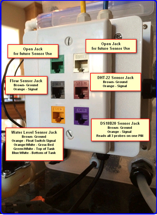
Here is the configuration of the left side of the connection box.

agponic-MD — features defined February 4, 2014
Posted by rik94566 in 1-wire, agponic MD, agponicMD, agponics.com, aquaponic automation, aquaponics, aquaponics electronics, DIY aquaponics, DS18B20, indoor aquaponics, indoor growing, Internet-of-Farming, IoT aquaponics, One-wire, PRODUCTS, Stainless Steel Temp Probe, Temperature Probe.Tags: 1-wire, aquaponic automation, automation, DIY aquaponics, DS18B20, indoor aquaponics, rik kretzinger, sensor, Temp Probe, Temperature Probe
2 comments
Now that the basic agponic-MD unit is completed – I am working through all the different features that can be found on the unit and define there functions.
Here is one side of the connection box at the back of the unit.

Connector Box on agponic-MD February 2, 2014
Posted by rik94566 in 1-wire, agponic MD, agponicMD, agponics.com, aquaponic automation, aquaponics, aquaponics electronics, arduino, DIY aquaponics, DS18B20, Float Sensor, Float Switch, indoor aquaponics, Internet-of-Farming, IoT aquaponics, One-wire, Rj45 connector, Slide Switch, Stainless Steel Temp Probe, SUGRU.Tags: 1-wire, aquaponic automation, Controlled Environment Agriculture, DIY aquaponics, DS18B20, indoor aquaponics, rik kretzinger, Temp Probe, Temperature Probe
add a comment
A big part of the aquaponic simulator is the fact that it uses standard RJ-45 jacks to interface with Arduino’s or a Raspberry PI. Having this type setup helps keep all the wires and connectors that are required for the unit to operate in a consistent manor safe and out of possible interaction with water elements.
Here is what is needed to construct this sub-assembly:

When all the above parts come together the finished product looks like this:
TOWER CORE GUTS – now for sale in “Things for sale” page September 26, 2013
Posted by rik94566 in agponics.com, aquaponic automation, aquaponics, aquaponics electronics, Internet-of-Farming, IoT aquaponics, Tower System, Tower Tubes, Tube Guts.Tags: aquaponic automation, DIY aquaponics, DS18B20, indoor aquaponics, microcontroller, rik kretzinger, sensor, Temperature Probe
5 comments
Here is what goes into the Tower Tubes and provides the water to the top and wiring for the sensor. The sensor configuration is a “Water Sensor” and “Temp Prob” combination. These have waterproof connectors that can be disconnected when the towers are removed to be taken to market or needing media to be pulled out once a crop is spent.


TOWER INTERFACE PLATE — protects the dry core of the tower base September 25, 2013
Posted by rik94566 in agponics.com, aquaponics, DIY aquaponics, DS18B20, Hacks, Interface Plate, One-wire, Sensor Hub, Tower System.Tags: 1-wire, aquaponic automation, DIY aquaponics, DS18B20, microcontroller, rik kretzinger
add a comment
Here is the “INTERFACE PLATE” — this plate is inserted into the base of the towers and is sealed. With this interface plate in place wires can be run to tower sensors and power supplied to the pumps that feed the towers. Without these interface plates it would be dangerous to provide power to pumps or connect or disconnect the tower columns.

DS18B20 – Terry King — Thank you July 12, 2013
Posted by rik94566 in 1-wire, aquaponics electronics, DIY aquaponics, DS18B20, One-wire, Stainless Steel Temp Probe.Tags: 1-wire, aquaponic automation, DS18B20, rik kretzinger, Temperature Probe
7 comments
Well thanks to Terry King and his comment – that he has DS18B20’s working fine with arduino IDE 1.0X. I double downed my efforts to get 1.0.2 arduino IDE working. I un-installed all versions – dumped all the libraries and started from a clean system again. Loaded everything up and got all the new libraries. EVERYTHING WORKED FINE! Thank you Terry!

What is an aquaponic device for IoT-aquaponics June 11, 2013
Posted by rik94566 in agponics.com, aquaponic automation, DIY aquaponics, DS18B20, Float Switch, IoT aquaponics, One-wire.Tags: aquaponic automation, aquaponics, DIY aquaponics, DS18B20, IoT, microcontroller, rik kretzinger, Temperature Probe
2 comments
Aquaponic devices can come in many sizes and shapes. There are simple and complex devices as with all technologies.
The most simple aquaponic device would be a temp probe connected up to an Arduino with the data generated being sent out to a Cloud service like Xively/Cosm/Pachube or ThingSpeak via ethernet or wireless connection.
I am working on a more complex aquaponic device right now that will contain the following sensor set:
pH sensor
3 – DS18B20 probes
1 – Flow meter
3 – media sensors
1 – Float Switch
1 – Humidity and Temp probe (DHT-22)
3 – gravity feed valves controlled by relays
1 – air pump controlled by relay (in N/O) configuration
1 – back-up air pump that turns on if electric goes out
1 – heater controlled by relays driven by temp reading being generated by the DS18B20 probes.
This device will be my proto-type to test sensor configurations and try new sensors out. It will allow me to gain an understanding of how all this IoT technology comes together and can actually perform work with out me having to constantly watch my system. I would like to be in Hawaii and just have my iPhone alert me when an event is out of range. Then I could make the necessary adjustments over my Aquaponic API software and be done with it while at the beach.
DS18B20 – always a new twist June 10, 2013
Posted by rik94566 in 1-wire, aquaponics electronics, DIY aquaponics, DS18B20, IoT aquaponics, One-wire, Stainless Steel Temp Probe, Temperature Probe.Tags: 1-wire, DIY aquaponics, DS18B20, IoT, rik kretzinger, sensor, Temp Probe, Temperature Probe
2 comments
I have resisted moving to Arduino IDE 1.0.x as I have read that people have had problems moving to it.
In my case I have been using ver 21 IDE because it was stable and all the libraries worked with it. Now that I am moving to the IoT platform I am required to use Arduino IDE 1.0.x.
First step was to download and install. Then needed to re-establish all the libraries required to work with DS18B20. Once all done it was time to determine if it all would work correctly.
To start off I ran the one-wire finder sketch. Much to my delight it worked. Now I was very confident that this transition was going to go smoothly. I now connected up 3 sensors and loaded my 3 sensor sketch.
Here was my result:

I got reading that were incorrect or really no readings at all
Next I had to make sure the hardware was connected right. So I went back to my ver. 21 IDE and re-tested everything. Sure enough everything worked great.
The results now is that using the Hacktronics sketch that was stated to be workable with Arduino IDE 1.0.x does not work with my set-up. Now I will have to determine just what the problem is and how to correct it.
This will have to be my next task in learning about the DS18B20 and Arduino.
