TIME TO STEP UP TO A BETTER TESTER March 21, 2021
Posted by rik94566 in aquaponic systems, aquaponics, Controlled Environment Agriculture, DIY aquaponics, general, Internet-of-Farming, IoT aquaponics, pH, rik kretzinger, rik.diy.IOT, rik94566.Tags: aquaponics, Bluelab, pH, rik-dyi-IOT, rik94566, tester
add a comment

For about 3 years I have been using a cheap pH tester. The main reason for using cheap units has been that I did not know the type and configuration that I wanted to purchase for the main unit that I would be using for many years to come. After the purchase of another testing probe made by Bluelab I started researching the pH options the Bluelab offered. As I found many different units that could be purchased for this purpose. So after some time and reading many reviews I selected the pH-PEN. Life has gotten much simpler with this purchase. More expensive YES – but I now save so much time as the calibration holds for a month and is very accurate every time I use the unit. So happy I selected this unit of very high quality and perfect for all my needs. I purchased the unit from Amazon.
HOME ASSISTANT — NODE-RED August 31, 2020
Posted by rik94566 in agponics.com, aquaponic automation, aquaponic systems, aquaponics, auqaponics automation, Controlled Environment Agriculture, DIY aquaponics, indoor aquaponics, internet of farming, Internet-of-Farming, Uncategorized.Tags: aquaponic automation, aquaponic devices, Home Assistant, Internet-of-Farming, Node-Red, rik kretzinger, rik-dyi-IOT, rik94566
add a comment
Researching how best to start learning Node-Red I spent a lot of time on YouTube watching what Node-Red is and how people learned how to use it. As always a lot of YouTuber’s put out content and some are clearly better at actually helping people understand concepts and produce valuable content that can be put to use by a non-computer programmer type person.
So I developed my list of people that were best for me to follow and start the process of learning this new skill set. Many of the ones I like were talking about the use of Node-Red with Home Assistant.
I had looked at Home Assistant some years ago and at the time it seemed Home Assistant was for very advanced users that are very good at the command prompt and with a lot of system knowledge. Way above my level at the time.
Then my research turned up this reference and changed my perspective on using Home Assistant.
This was, just what I was looking for.
Been looking for a better way – DS18B20 October 15, 2019
Posted by rik94566 in 1-wire, agponics.com, aquaponic devices, aquaponics electronics, arduino, auqaponics automation, Balcony aquaponics, Balcony Garden, Controlled Environment Agriculture, DIY aquaponics, DS18B20, ds18b20, Electronic Componets, internet of farming, Internet-of-Farming, IoT aquaponics, rik kretzinger, rik.diy.IOT, rik94566, sensor, Stainless Steel Temp Probe, Temperature Probe.Tags: agponics, aquaponics, DIY aquaponics, DS18B20, DS18B20 aquaponics, Internet-of-Farming, rik, rik94566, sensor
3 comments
I was doing some research on a totally different subject and this popped up.

Why this one?
Well easy answer – I have been making my own 4.7 pull-up resistor connectors for sometime now. Problem for me is that they take a lot of time and are very bulky and hard to work with. For a little more cost a dollar or so I get a board that will allow easy connections to many (so I think) DS18B20 sensors using one resistor. The order came and now I can start testing my idea. Having a solution this turn key will save a lot of time and perform better, time will tell now.
I will be posting how the testing goes and what will be needed to get top performance out of this module.
Technology is complicated — May 8, 2015
Posted by rik94566 in Controlled Environment Agriculture, DIY aquaponics, Electronic Componets, indoor aquaponics, IoT aquaponics, Temperature Probe.Tags: agponics, aquaponic automation, aquaponics, arduino, arduino sketch, automation, DIY aquaponics, indoors aquaponics, microcontroller, rik kretzinger, Temboo, YUN
add a comment
I say this because I will be displaying my aquaponic – IoT – Balcony Unit at Maker Faire next week in San Mateo. To accomplish the IoT part of the build I have to use technology that allows for internet communication thus IoT! Well there are many options available to accomplish this task – some not so easy and others not enough features to be effective for this project.
So my choice in this case is the Arduino YUN —

I made this choice because I had one (but had not used it as yet) and the fact that documentation on it is easy to find. The other fact is that Temboo www.temboo.com uses the YUN as one of its options for their solution to the Internet of Things and I am working with them on this open source project so many others will be able to get up and running in short order and have simpler options to add additional capability based on the persons needs and I will not have to supply the customer support for any aspect of the code other than give everyone a stating point.
WELL – that is where things got interesting.
Had to work through getting the YUN on the network of choice. Not a big deal but it took some time and many attempts to get it dialed in because the Arduino instructions tell you to go to arduino.local to find the individual unit. Well this only works about 60% of the time. So the solution is to use the IP address of 192.168.24.1 now I could configure the thing to my liking. Once configured it would not show up in the Arduino IDE at all. Major issue for me as I had no idea if the unit configured or not. I finally when on to my wireless router to see if the board was being recognized. Had to dig out all the USER ID and PASSWORD info and then work through all the menus to determine what in fact was connected to the router. There is was — YEA
Now I had to research out why it was not listed as a port option in my Arduino IDE. Well after some time and deep research I found that Arduino IDE only works some times for the YUN on wireless. So the uploading from Arudino IDE to the board is not an option as most of the YouTube videos demonstrate quite well. This becomes an issue because I found out that as configured the YUN does not have enough on board memory, so a SD card is needed.
Using an SD card with the YUN requires that the card be format using the YUN. To do that you need to know that the YUN is connected to the internet and working properly which is very hard to know if it is or not.
So once you know the YUN is connected and you have it connected through cable to your computer you need a file called ” YunDiskSpaceExpander” found on the Arduino site. Once uploaded you access it through the Serial Monitor of the Arduino IDE. If all goes well you answer a bunch of cryptic questions and bingo the thing kicks off. Once do you have a formated YUN SD enabled board.
Now I am ready for the real fun stuff to generate code to be used through Temboo so I will have “Streaming Data” and text messaging in short order – lets hope!
The good news in all of this is that I will be documenting all of this for the instructions to the Balcony unit for all to use and save anyone interested in building one or gets a kit from me that will be up and running in short order.
See you all at Maker Faire next Saturday if you make it there!
aquaponic- IoT device — Balcony Garden March 10, 2015
Posted by rik94566 in aquaponic automation, aquaponics, Balcony aquaponics, Controlled Environment Agriculture, DS18B20.Tags: agponics, aquaponic automation, aquaponics, arduino, automation, balcony aquaponics
add a comment
BALCONY AQUAPONIC GARDEN – IoT READY- DIY or purchase materials locally and build — by rik kretzinger


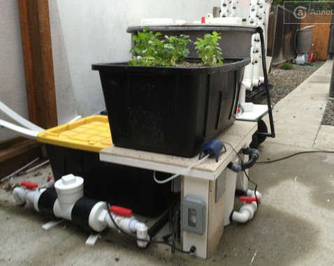
RADIAL FLOW FILTER – just completed April 2, 2014
Posted by rik94566 in agponics.com, aquaponic automation, aquaponics, aquaponics electronics, Controlled Environment Agriculture, DIY aquaponics, Electronic Componets, indoor aquaponics, Internet-of-Farming, IoT aquaponics, PRODUCTS, radial flow filter, Tower System.Tags: aquaponic automation, automation, Controlled Environment Agriculture, DIY aquaponics, indoors aquaponics, IoT, microcontroller, rik kretzinger
add a comment
 Since first conceiving of the Tower unit as a concept I knew they needed to be operated differently than DWC and Media bed in how you deal with the solids from the fish. Media beds — it has not been that big a deal for me because my rule is that any tank size smaller than 350 I filter the water and break-up the solids and then put back into solution by pumping back into the grow beds. This way I lose no nutrients that the fish produce. Has worked well for over 3 years now. In the testing that I have done with the towers I found that solids need to be dealt with or things will plug up. I still will be reintroducing the broken up solids back into the system put it will take place downstream of the bio-filter component and re-injected into the new buffer tank that stabilizes fish tank water volume and height. This all came out of research I was doing on how best to handle solids in aquaponics. As designed this radial flow filter can handle up to and maybe a bit more than a 1000 gallons of fish tank water. The only thing left to figure out on this radial flow filter now is where I will be locating the outlet for the clean water. That will be dependent on fish tank water level. Should have fish tank completed this coming weekend and make the determination on this aspect of the build.
I put together a youtube slide show if you want to see more detail of the radial flow filter:
SENSOR COLOR CODE – for tracking where the probes are in the towers December 9, 2013
Posted by rik94566 in agponics.com, aquaponic automation, aquaponics, Controlled Environment Agriculture, DIY aquaponics, DS18B20, IoT aquaponics, Tower System, Tower Tubes.Tags: aquaponic automation, aquaponic crop, DIY aquaponics, rik kretzinger, sensor
2 comments
Since I have a larger number of sensors in each tower unit I needed a way to know the exact sensor I will be dealing with and the location of the sensor. The best way for me is to mimic the electronic color codes found on resistors. Why reinvent things if I don’t have to. So here is how I solved this problems.

So let now see how this works out —
 Here is the layout of the color coding for these sensors located in tower tube –
Temp Probes are – BLUE color
Water Probes are – YELLOW color
Start the code at the Sensor position and work into the inter-core


These patterns are repeated on both ends of the cable with the outer most position being the sensor color. So if you held the two ends up together with the connectors facing the same direction then the code would mirror each other.
BEST COMMENT OF THE YEAR — from “Internet of Farming” September 16, 2013
Posted by rik94566 in agponics.com, aquaponic automation, aquaponics, aquaponics electronics, arduino, CEA, Controlled Environment Agriculture, Internet-of-Farming, IoT aquaponics.Tags: aquaponic automation, automation, CEA, Controlled Environment Agriculture, DIY aquaponics, indoor aquaponics, microcontroller, rik kretzinger, sensor
add a comment
![]()
I am a aquatic live system specialist, built systems around the world all sizes and types!
and I just want to say that you did impress me a lot!
you are a genius! this whole entire thing is wow!

DS18B20 — external power supply December 15, 2011
Posted by rik94566 in 1-wire, aquaponic automation, aquaponics, arduino, CEA, Controlled Environment Agriculture, DIY aquaponics, DS18B20, HEX code, indoor aquaponics, indoor gardens, indoor growing, One-wire, probe index, sensor, Sensor Hub, Stainless Steel Temp Probe, Temperature Probe.Tags: 1-wire, aquaponic automation, aquaponic crop, arduino, arduino sketch, automation, CEA, Controlled Environment Agriculture, DIY aquaponics, DS18B20, electronics, indoor aquaponics, indoors aquaponics, microcontroller, rik kretzinger, sensor, Temp Probe, Temperature Probe
1 comment so far
Before I can connect everything up and work with my DS18B20 probes using external power supply I need to get one. The one that I have selected is this one:

5V power supply
DS18B20 – on to external power December 7, 2011
Posted by rik94566 in 1-wire, aquaponic automation, aquaponics, arduino, CEA, Controlled Environment Agriculture, DIY aquaponics, DS18B20, HEX code, indoor aquaponics, indoor gardens, indoor growing, One-wire, probe index, sensor, Sensor Hub, Stainless Steel Temp Probe, Temperature Probe.Tags: 1-wire, aquaponic automation, aquaponic crop, aquaponics, arduino, arduino sketch, automation, CEA, Controlled Environment Agriculture, DIY aquaponics, DS18B20, ds18b20 water proof, electronics, indoor aquaponics, microcontroller, rik kretzinger, sensor, Temp Probe, Temperature Probe, water proof temp probe
2 comments

When you want to learn something new in electronics, you have to start at the bottom. In my mind a circuit layout like this is the bottom for me and it is hard for me to follow. I will be the first to admit that I am not an electrical engineer and don’t want to be one either. I just want a simple way to hook things up and have them work when I need them too. So this layout just gives me a general idea of where to start on hooking up a external power source for my probes. I was at this same point when I started to learn about DS18B20’s and use with an arduino. The good news is that I have a more clear understanding how the DS18B20 functions and how it operates than when I first started on this project.
WHY DO I NEED EXTERNAL POWER FOR MY DS18B20’S ——-
Well that is a very good questions. In most applications and small projects you do not need to know anything about this aspect of the DS18B20’s. In my case as I have been working on this blog several questions have been posed as to power drains on arduino’s if you request to many sensors being driven by the unit and you have long runs to your sensors. So I need to do some research as to how to use a external power source. A lot of places on the internet talk about it, but I have yet to find any source that shows a person how to actually make this work. As for the research here is the best I could find. If you know of others please let me know and I will add it to my library and give you credit for it here.
HERE IS THE BIBLE ON THIS SUBJECT —
http://www.arduino.cc/playground/Learning/OneWire
Normal (external supply) mode
With an external supply, three wires are required: the bus wire, ground, and power. The 4.7k pull-up resistor is still required on the bus wire. As the bus is free for data transfer, the microcontroller can continually poll the state of a device doing a conversion. This way, a conversion request can finish as soon as the device reports being done, as opposed to having to wait 750ms in “parasite” power mode.
Note on resistors: For larger networks, you can try something smaller. The ATmega328/168 datasheet indicates starting at 1k6 and a number of users have found smaller to work better on larger networks.
THAT IS ALL THERE IS — in this bible. Not much of a help in my mind.
HERE IS THE OTHER THING I FOUND:
http://sheepdogguides.com/dst9parasitic.htm
Choosing your 1-Wire chip power mode
Many of the chips in the 1-Wire family from Dallas Semiconductor can be powered “parasitically”… that’s Dallas’s (apt) name for the system used.
The advantage of parasitic powering is that it means you can have a two wire MicroLan. (“MicroLan” is just Dallas’s trademarked name for a bunch of 1-Wire chips “playing nicely” with each other and a “master” device, e.g. a PC or simple microcontroller, e.g. Arduino, in charge of the network of 1-Wire sensors, actuators, storage units, etc.) If you don’t use parasitic powering, then you need to run three wires from chip to chip to chip. (An aside: You should be aware that MicroLans don’t like star topographies. If you need a star, you need a hub to split it into separate, non- star, legs.)
I’ve often used parasitic powering entirely successfully. However, if you have a lot of chips on the MicroLan, or high poll rates, the time may come when supplying the chips which can be powered parasitically makes sense. It isn’t difficult… especially if you provided for the possibility that you’d like to make the change when you first set up your MicroLan.
For example…
Just as an example, let’s consider a MicroLan that is reading temperatures in various parts of a large greenhouse.
We’ll assume you’re using chips from the DS182x family, in a TO92 package, the little blob of plastic with three “legs”.
To use those chips parasitically, you just connect two of the legs to one another, and that leaves you with two connections which go to the two wires of the basic MicroLan.
Now… and this is what I meant about giving yourself options for the future… rather than doing that the “obvious” way, using either a small PCB, or simple discrete wires, connect each of the three pins to a separate track or wire, and THEN make your connections to the MicroLan. If later, you want to use non parasitic power, then all you have to do is change a link, or disconnect one of the wires, and you can then supply the chip with its independent V,cc easily, without disturbing what would be fiddly connections to the package’s pins.
Here are the details of which pin is which on the DS1820…

The DS1820’s middle leg goes to the 1-Wire data line.
The DS1820’s leg marked “See text” should be attached to the 5v, or, for parasitic power, connect this pin to ground (zero volts))
And the DS1820’s “1-Wire 0v” should be attached ground,i.e. to zero volts.
(If the above seems over-explained, please remember that this page may be accessed by people who want more than just an idea of what this “parasitic power” thing is all about.)
AND THE LAST ONE I FOUND:
http://forums.parallax.com/showthread.php?135523-ds18b20-sensor-fails-at-high-temperature
- osts
- 117
 Re: ds18b20 sensor fails at high temperature
I may have stumbled on a possible solution, but I am not sure how to code it. The snippet below is from the Maxim data sheet for the ds18b20. If I understand the second paragraph, correctly, I may need to Insert these commands:
Skip rom (cch)
Read power (b4h)
Then initiate a “read time slot”I am not sure how or where to insert these commands in the one wire object.
I am using an external power supply with a 4.7k pullup“The use of parasite power is not recommended for temperatures above +100°C since the DS18B20 may not be able to sustain communications due to the higher leakage currents that can exist at these temperatures. For applications in which such temperatures are likely, it is strongly recommended that the DS18B20 be powered by an external power supply.
In some situations the bus master may not know whether the DS18B20s on the bus are parasite powered or powered by external supplies. The master needs this information to determine if the strong bus pullup should be used during temperature conversions. To get this information, the master can issue a Skip ROM [CCh] command followed by a Read Power Supply [B4h] command followed by a “read time slot”. During the read time slot, parasite powered DS18B20s will pull the bus low, and externally powered DS18B20s will let the bus remain high. If the bus is pulled low, the master knows that it must supply the strong pullup on the 1-Wire bus during temperature conversions.
Not a lot to work with here, but I do have a lay out and now need to assemble the components I will need to pull this off. Don’t you just love electronics and all the neat stuff you get to learn!!!!
