DS18B20 – Resistor Module – parts defined November 4, 2019
Posted by rik94566 in 1-wire, agponics.com, aquaponic devices, aquaponics electronics, auqaponics automation, DIY aquaponics, DS18B20, ds18b20, Electronic Componets, indoor aquaponics, internet of farming, Internet-of-Farming, IoT aquaponics, One-wire, rik kretzinger, rik.diy.IOT, rik94566.Tags: aquaponic automation, aquaponic devices, aquaponic electronics, aquaponic sensors, aquaponics, DS18B20, DS18B20 aquaponics, ds18b20 water proof, Internet-of-Farming, rik, rik-dyi-IOT, rik94566, sensors
6 comments
Working with the resistor module is making things much easier and a lot less work on my part. I am liking what I am seeing from a development standpoint and can see a real time savings that will deliver consistent results. First step is understanding what is found on the board and which end goes with which connection.

Been looking for a better way – DS18B20 October 15, 2019
Posted by rik94566 in 1-wire, agponics.com, aquaponic devices, aquaponics electronics, arduino, auqaponics automation, Balcony aquaponics, Balcony Garden, Controlled Environment Agriculture, DIY aquaponics, DS18B20, ds18b20, Electronic Componets, internet of farming, Internet-of-Farming, IoT aquaponics, rik kretzinger, rik.diy.IOT, rik94566, sensor, Stainless Steel Temp Probe, Temperature Probe.Tags: agponics, aquaponics, DIY aquaponics, DS18B20, DS18B20 aquaponics, Internet-of-Farming, rik, rik94566, sensor
3 comments
I was doing some research on a totally different subject and this popped up.

Why this one?
Well easy answer – I have been making my own 4.7 pull-up resistor connectors for sometime now. Problem for me is that they take a lot of time and are very bulky and hard to work with. For a little more cost a dollar or so I get a board that will allow easy connections to many (so I think) DS18B20 sensors using one resistor. The order came and now I can start testing my idea. Having a solution this turn key will save a lot of time and perform better, time will tell now.
I will be posting how the testing goes and what will be needed to get top performance out of this module.
800 X 480 – 5″ HDMI display – Jessie with Pixel – resolution issue – Raspberry Pi March 16, 2017
Posted by rik94566 in 800 X 480 display, adafruit, aquaponic automation, aquaponics electronics, Balcony Garden, DIY aquaponics, Electronic Componets, indoor aquaponics, Instructables, IoT aquaponics, Raspberry PI, rik kretzinger, rik94566.add a comment

This display was purchased to allow a graphical interface element to the automation effort of aquaponic systems. So I was very happy to find this display and it could easily be integrated into the overall design with a very small footprint.
ADAFRUIT is quite clear that that this 5″ HDMI display will not work without changes to the “config.txt” file to set-up for the different display size. In this case 800 X 480 resolution. The documentation to make these changes is very good and works as documented.
THAT IS UNTIL A NEW RELEASE OF RASPBERRY PI OS —
As always technology never stands still. Advances are made almost daily when it comes to Raspberry Pi and the OS is no exception. In late 2016 a new upgrade was rolled out called “JESSIE” with Pixel. There was a lot of buzz about this new upgrade and it does look and perform much better over all. Once you upgrade or update there is no going back.
The problem with the “JESSIE” upgrade is that now the solution provide by ADAFRUIT for the 5″ HDMI display no longer worked very well and was unusable as a display on the Balcony Gardens.
A fix was needed, but since “JESSIE” was so new no one was really aware of this resolution issue and the resolution issue was not even being talked about on ADAFRUIT site or in the Raspberry Pi forums.
After a lot of searching and months later a solution was found.
Long story so I will not go into details of the issue, but have documented it all in an Instructable that can be found here:
Instructable – 800 X 480 5″ HDMI display – resolution issue
HERE IS THE FIX AND LINK TO THE SOLUTION:
Actual changes needed in the “config.txt” file for use:
In the file /boot/config.txt add the following text to the end of the file:
#increase HDMI signal strength
config_hdmi_boost=4
#remove black borders
disable_overscan=1
#set specific CVT mode
hdmi_cvt 800 480 60 6 0 0 0
#set CVT as default
hdmi_group=2
hdmi_mode=87
dtoverlay=ads7846,cs=1,penirq=25,penirq_pull=2,speed=50000,keep_vref
_on=0,swapxy=0,pmax=255,xohms=150,xmin=200,xmax=3900,
ymin=200,ymax=3900
dtoverlay=w1-gpio-pullup,gpiopin=4,extpullup=1
Save the config file and then do this: (see note below about this one)
sudo apt -get install xinput-calibrator
I have not tried using the above install command, because I was able to gain the results I needed without it. I believe like Auvy that sometimes less is more!
HERE IS THE LINK TO THE SOLUTION AS SHOWN ABOVE:
AMAZON SOLUTION – 5″ HDMI display – JESSIE – Pixel – resolution issue
Technology is complicated — May 8, 2015
Posted by rik94566 in Controlled Environment Agriculture, DIY aquaponics, Electronic Componets, indoor aquaponics, IoT aquaponics, Temperature Probe.Tags: agponics, aquaponic automation, aquaponics, arduino, arduino sketch, automation, DIY aquaponics, indoors aquaponics, microcontroller, rik kretzinger, Temboo, YUN
add a comment
I say this because I will be displaying my aquaponic – IoT – Balcony Unit at Maker Faire next week in San Mateo. To accomplish the IoT part of the build I have to use technology that allows for internet communication thus IoT! Well there are many options available to accomplish this task – some not so easy and others not enough features to be effective for this project.
So my choice in this case is the Arduino YUN —

I made this choice because I had one (but had not used it as yet) and the fact that documentation on it is easy to find. The other fact is that Temboo www.temboo.com uses the YUN as one of its options for their solution to the Internet of Things and I am working with them on this open source project so many others will be able to get up and running in short order and have simpler options to add additional capability based on the persons needs and I will not have to supply the customer support for any aspect of the code other than give everyone a stating point.
WELL – that is where things got interesting.
Had to work through getting the YUN on the network of choice. Not a big deal but it took some time and many attempts to get it dialed in because the Arduino instructions tell you to go to arduino.local to find the individual unit. Well this only works about 60% of the time. So the solution is to use the IP address of 192.168.24.1 now I could configure the thing to my liking. Once configured it would not show up in the Arduino IDE at all. Major issue for me as I had no idea if the unit configured or not. I finally when on to my wireless router to see if the board was being recognized. Had to dig out all the USER ID and PASSWORD info and then work through all the menus to determine what in fact was connected to the router. There is was — YEA
Now I had to research out why it was not listed as a port option in my Arduino IDE. Well after some time and deep research I found that Arduino IDE only works some times for the YUN on wireless. So the uploading from Arudino IDE to the board is not an option as most of the YouTube videos demonstrate quite well. This becomes an issue because I found out that as configured the YUN does not have enough on board memory, so a SD card is needed.
Using an SD card with the YUN requires that the card be format using the YUN. To do that you need to know that the YUN is connected to the internet and working properly which is very hard to know if it is or not.
So once you know the YUN is connected and you have it connected through cable to your computer you need a file called ” YunDiskSpaceExpander” found on the Arduino site. Once uploaded you access it through the Serial Monitor of the Arduino IDE. If all goes well you answer a bunch of cryptic questions and bingo the thing kicks off. Once do you have a formated YUN SD enabled board.
Now I am ready for the real fun stuff to generate code to be used through Temboo so I will have “Streaming Data” and text messaging in short order – lets hope!
The good news in all of this is that I will be documenting all of this for the instructions to the Balcony unit for all to use and save anyone interested in building one or gets a kit from me that will be up and running in short order.
See you all at Maker Faire next Saturday if you make it there!
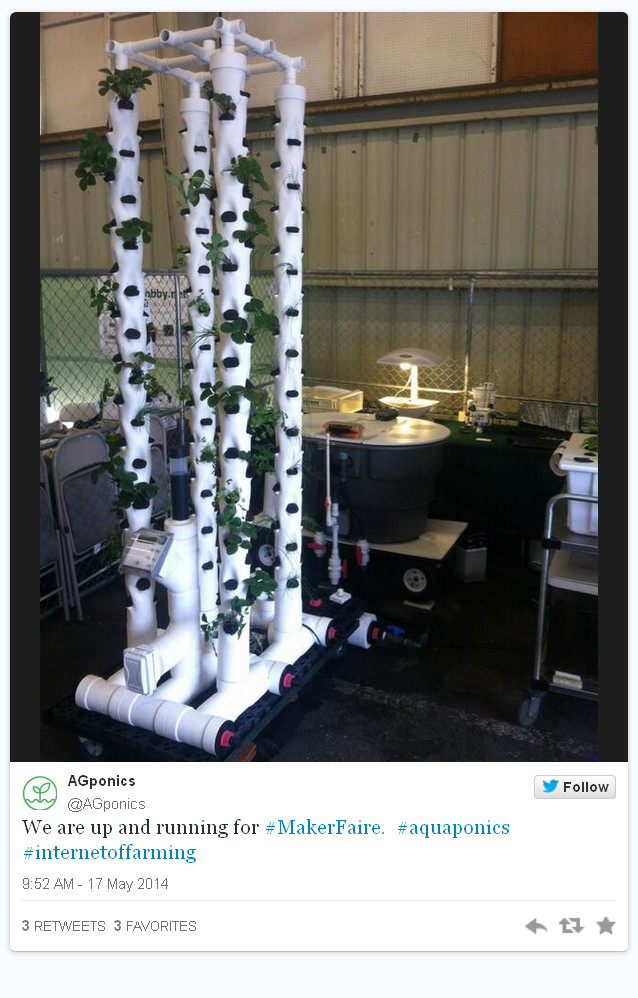
TOWER SYSTEM – set-up at Maker Faire 2014 May 22, 2014
Posted by rik94566 in adafruit, agponics.com, arduino, DIY aquaponics, DS18B20, Electronic Componets, indoor aquaponics, indoor gardens, indoor growing, Internet-of-Farming, IoT aquaponics, One-wire, Raspberry PI, Tower System, Tower Tubes.Tags: agponics, aquaponics, automation, Controlled Environment Agriculture, DIY aquaponics, indoor aquaponics, IoT, Maker Faire, microcontroller, rik kretzinger, sensor
2 comments
RADIAL FLOW FILTER – just completed April 2, 2014
Posted by rik94566 in agponics.com, aquaponic automation, aquaponics, aquaponics electronics, Controlled Environment Agriculture, DIY aquaponics, Electronic Componets, indoor aquaponics, Internet-of-Farming, IoT aquaponics, PRODUCTS, radial flow filter, Tower System.Tags: aquaponic automation, automation, Controlled Environment Agriculture, DIY aquaponics, indoors aquaponics, IoT, microcontroller, rik kretzinger
add a comment
 Since first conceiving of the Tower unit as a concept I knew they needed to be operated differently than DWC and Media bed in how you deal with the solids from the fish. Media beds — it has not been that big a deal for me because my rule is that any tank size smaller than 350 I filter the water and break-up the solids and then put back into solution by pumping back into the grow beds. This way I lose no nutrients that the fish produce. Has worked well for over 3 years now. In the testing that I have done with the towers I found that solids need to be dealt with or things will plug up. I still will be reintroducing the broken up solids back into the system put it will take place downstream of the bio-filter component and re-injected into the new buffer tank that stabilizes fish tank water volume and height. This all came out of research I was doing on how best to handle solids in aquaponics. As designed this radial flow filter can handle up to and maybe a bit more than a 1000 gallons of fish tank water. The only thing left to figure out on this radial flow filter now is where I will be locating the outlet for the clean water. That will be dependent on fish tank water level. Should have fish tank completed this coming weekend and make the determination on this aspect of the build.
I put together a youtube slide show if you want to see more detail of the radial flow filter:
agponic MD – connecton box left side features February 12, 2014
Posted by rik94566 in agponic MD, agponicMD, agponics.com, aquaponic automation, aquaponics, aquaponics electronics, arduino, DIY aquaponics, DO sensor, indoor aquaponics, indoor growing, Internet-of-Farming, IoT aquaponics, One-wire, PRODUCTS, Slide Switch, Slide Switch.Tags: aquaponic automation, aquaponic crop, DIY aquaponics, DS18B20, indoor aquaponics, microcontroller, rik kretzinger, Temp Probe
add a comment
Here is the configuration of the left side of the connection box.

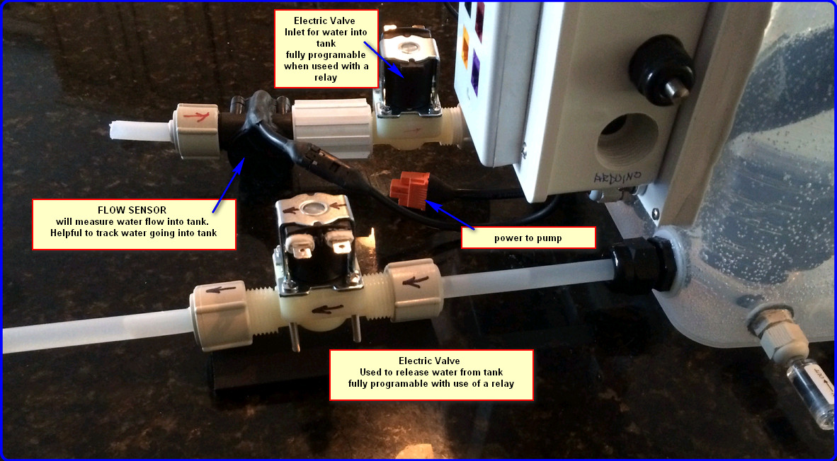
Backside equipment found on agponic-MD unit February 2, 2014
Posted by rik94566 in agponic MD, agponicMD, aquaponic automation, aquaponics, arduino, DIY aquaponics, Electronic Componets, Gravity feed valves, plumbing, sensor.Tags: arduino sketch, automation, DIY aquaponics, indoor aquaponics, IoT, rik kretzinger, sensor
3 comments
2013 in review December 31, 2013
Posted by rik94566 in agponics.com, aquaponic automation, aquaponics, aquaponics electronics, arduino, CEA, DIY aquaponics, Electronic Componets.Tags: aquaponic automation, aquaponic crop, CEA, DIY aquaponics, indoor aquaponics, microcontroller, rik kretzinger, sensor
add a comment
2013 annual report for aquaponic DIY Automation blog.

Here’s an excerpt:
The concert hall at the Sydney Opera House holds 2,700 people. This blog was viewed about 35,000 times in 2013. If it were a concert at Sydney Opera House, it would take about 13 sold-out performances for that many people to see it.
Slide Switch – wire configuration complete April 14, 2013
Posted by rik94566 in agponics.com, aquaponic automation, aquaponics, aquaponics electronics, DIY aquaponics, indoor aquaponics, IoT aquaponics, Slide Switch.Tags: aquaponic automation, aquaponics, DIY aquaponics, IoT, rik kretzinger
add a comment
Here is how I did my slide switch so I could move from two different power sources. It worked the way I thought it would, but until I actually connect things up I am never sure. The basic concept is that all positive (RED) wires come off one side of the switch and the negative (BLACK) wires come off the other side. It does not matter which is which, you just need to be consistent so you can duplicate the results on future projects. Each one of the power sources are at the ends of the slide switch. Again it does not matter how you connect it up, but each source needs to be opposite of each other. Configured this way the center prongs will be passed power depending on which end you have the slide positioned.

“SLIDE SWITCH LAYOUT”
