agponic MD – connecton box left side features February 12, 2014
Posted by rik94566 in agponic MD, agponicMD, agponics.com, aquaponic automation, aquaponics, aquaponics electronics, arduino, DIY aquaponics, DO sensor, indoor aquaponics, indoor growing, Internet-of-Farming, IoT aquaponics, One-wire, PRODUCTS, Slide Switch, Slide Switch.Tags: aquaponic automation, aquaponic crop, DIY aquaponics, DS18B20, indoor aquaponics, microcontroller, rik kretzinger, Temp Probe
add a comment
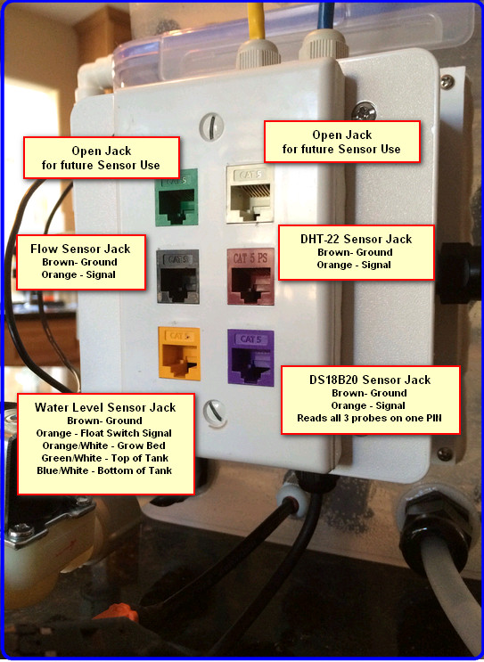
Here is the configuration of the left side of the connection box.

agponic-MD — features defined February 4, 2014
Posted by rik94566 in 1-wire, agponic MD, agponicMD, agponics.com, aquaponic automation, aquaponics, aquaponics electronics, DIY aquaponics, DS18B20, indoor aquaponics, indoor growing, Internet-of-Farming, IoT aquaponics, One-wire, PRODUCTS, Stainless Steel Temp Probe, Temperature Probe.Tags: 1-wire, aquaponic automation, automation, DIY aquaponics, DS18B20, indoor aquaponics, rik kretzinger, sensor, Temp Probe, Temperature Probe
2 comments
Now that the basic agponic-MD unit is completed – I am working through all the different features that can be found on the unit and define there functions.
Here is one side of the connection box at the back of the unit.

200,000 Views on Youtube – “Internet of Farming” — WOW February 2, 2014
Posted by rik94566 in agponics.com, aquaponic automation, aquaponics, Crop, DIY aquaponics, Internet-of-Farming, IoT aquaponics, Tower System.Tags: aquaponic crop, automation, Controlled Environment Agriculture, DIY aquaponics, indoor aquaponics, IoT, LED aquaponics, microcontroller, rik kretzinger, Temp Probe, Temperature Probe
add a comment

Connector Box on agponic-MD February 2, 2014
Posted by rik94566 in 1-wire, agponic MD, agponicMD, agponics.com, aquaponic automation, aquaponics, aquaponics electronics, arduino, DIY aquaponics, DS18B20, Float Sensor, Float Switch, indoor aquaponics, Internet-of-Farming, IoT aquaponics, One-wire, Rj45 connector, Slide Switch, Stainless Steel Temp Probe, SUGRU.Tags: 1-wire, aquaponic automation, Controlled Environment Agriculture, DIY aquaponics, DS18B20, indoor aquaponics, rik kretzinger, Temp Probe, Temperature Probe
add a comment
A big part of the aquaponic simulator is the fact that it uses standard RJ-45 jacks to interface with Arduino’s or a Raspberry PI. Having this type setup helps keep all the wires and connectors that are required for the unit to operate in a consistent manor safe and out of possible interaction with water elements.
Here is what is needed to construct this sub-assembly:

When all the above parts come together the finished product looks like this:
DS18B20 – always a new twist June 10, 2013
Posted by rik94566 in 1-wire, aquaponics electronics, DIY aquaponics, DS18B20, IoT aquaponics, One-wire, Stainless Steel Temp Probe, Temperature Probe.Tags: 1-wire, DIY aquaponics, DS18B20, IoT, rik kretzinger, sensor, Temp Probe, Temperature Probe
2 comments
I have resisted moving to Arduino IDE 1.0.x as I have read that people have had problems moving to it.
In my case I have been using ver 21 IDE because it was stable and all the libraries worked with it. Now that I am moving to the IoT platform I am required to use Arduino IDE 1.0.x.
First step was to download and install. Then needed to re-establish all the libraries required to work with DS18B20. Once all done it was time to determine if it all would work correctly.
To start off I ran the one-wire finder sketch. Much to my delight it worked. Now I was very confident that this transition was going to go smoothly. I now connected up 3 sensors and loaded my 3 sensor sketch.
Here was my result:

I got reading that were incorrect or really no readings at all
Next I had to make sure the hardware was connected right. So I went back to my ver. 21 IDE and re-tested everything. Sure enough everything worked great.
The results now is that using the Hacktronics sketch that was stated to be workable with Arduino IDE 1.0.x does not work with my set-up. Now I will have to determine just what the problem is and how to correct it.
This will have to be my next task in learning about the DS18B20 and Arduino.
DS18B20 – ground connectors now complete August 15, 2012
Posted by rik94566 in 1-wire, DS18B20, One-wire, Sensor Hub, Stainless Steel Temp Probe.Tags: 1-wire, automation, DIY aquaponics, microcontroller, rik kretzinger, sensor, Temp Probe, Temperature Probe
2 comments

Ground connectors completed and tested
I am getting closer to getting 20 probes ready to test. Everything is just about in place to make a run at it. So stay tuned we are getting close now…….
DS18B20 — new probe set established August 13, 2012
Posted by rik94566 in 1-wire, aquaponic automation, aquaponics, DIY aquaponics, DS18B20, HEX code.Tags: 1-wire, aquaponic automation, DIY aquaponics, DS18B20, rik kretzinger, Temp Probe, Temperature Probe
2 comments
Next step in getting to determine if I can get 20 probes to configure correctly, is to determine the HEX code for each probe. Being that I had 10 left to pull of the HEX I got to work on this task. Here are the results.
P022 — 0x28, 0x67, 0x22, 0x47, 0x03, 0x00, 0x00, 0xA1
P023 — 0x28, 0xAC, 0x30, 0x47, 0x03, 0x00, 0x00, 0x39
P024 — 0x28, 0x4A, 0x18, 0x47, 0x03, 0x00, 0x00, 0x64
P025 — 0x28, 0x1A, 0x3A, 0x47, 0x03, 0x00, 0x00, 0x31
P026 — 0x28, 0x66, 0xC1, 0x7A, 0x03, 0x00, 0x00, 0xD7
P027 — 0x28, 0xA2, 0x51, 0x47, 0x03, 0x00, 0x00, 0xF6
P028 — 0x28, 0xB5, 0x1F, 0x47, 0x03, 0x00, 0x00, 0x63
P029 — 0x28, 0x9B, 0xC0, 0x7A, 0x03, 0x00, 0x00, 0x22
P030 — 0x28, 0xBE, 0xB6, 0x7A, 0x03, 0x00, 0x00, 0x8E
P031 — 0x28, 0x20, 0x15, 0x47, 0x03, 0x00, 0x00, 0x84
Now I have the HEX code I need to enter all the information into my INDEX of probes so I can track each probe and where I have them located in my systems. Helpful to know if I move them around in the future. I had been using the procuct “MANYMOON” for tracking, but have since switched over to “EVERNOTE”. This has proved to be a better platform for me as I can manage larger amount of information on a large amount of projects. Evernote also allows me to have access to my information on any device I am using. Great Stuff.
Here is what my index now looks like:

Probe Set Index
DS18B20 — 4.7K connectors completed August 9, 2012
Posted by rik94566 in 1-wire, aquaponic automation, DS18B20, Stainless Steel Temp Probe.Tags: 1-wire, aquaponic automation, arduino, DIY aquaponics, rik kretzinger, sensor, Temp Probe
add a comment

4 – completed connectors and fully tested
The next step to achieving running 20 probes was to complete the 4.7K resistor harness set-up. I now have this done and can move on to the finishing off the ground connector that will allow pull all this together.
HARNESS TESTING — very important — DS18B20 April 20, 2012
Posted by rik94566 in 1-wire, aquaponic automation, DS18B20, One-wire, sensor, Stainless Steel Temp Probe, Temperature Probe.Tags: 1-wire, aquaponic automation, DIY aquaponics, DS18B20, microcontroller, rik kretzinger, sensor, Temp Probe, Temperature Probe
add a comment

use your multimeter
Now that I have constructed an addition harness I need to make sure it works. Two (2) tests needs to be performed. Conductivity and ohm confirmation of the resistor value through the connections.
CONDUCTIVITY:
This test will let me know that all my connections are correctly connected and signal is flowing through the wires and working the way I configured them. If not, I will need to correct the problem and retest until the connections are working correctly.
Here is a video of the testing I did:
ohm Value Testing:
This is important with DS18B20 probes. It is important because the DS18B20 IC’s are sensitive when it comes to resistor values and there tolerance levels. I bought some very cheap 4.7K ohm resistors and did not know the tolerance level. Hooked everything up and the probe did not work. I had to trouble shoot all the connections and everything was working – then I swapped out a resistor that I knew worked and had specs on and bingo everything was working. I have no problems using resistors with a 5% tolerance rating. They will give you some swings in value readings, but the DS18B20’s will work very well it you stay in this tolerance range.
Here is a video of how I tested for ohm’s:
Now on to building another harness and test it all
DS18B20 — external power – 5 Probes working April 6, 2012
Posted by rik94566 in 1-wire, aquaponic automation, arduino, DS18B20, One-wire, sensor, Stainless Steel Temp Probe.Tags: 1-wire, aquaponic automation, arduino sketch, automation, DIY aquaponics, DS18B20, rik kretzinger, sensor, Temp Probe
4 comments
Once I got the ground problem worked out and was reading one probe adding 4 more was no sweat…….

5 probe configuration
Here is the sketch I used: ( you will need to change out the HEX code parts for your specific DS18B20)
// This Arduino sketch reads DS18B20 “1-Wire” digital
// temperature sensors.
// Tutorial:
// http://www.hacktronics.com/Tutorials/arduino-1-wire-tutorial.html
//Changed sketch to handle individual temperature probes for testing out software and hub
//each probe is plugged into a wiring harness using either a 4.7K or 2.2K resistor configuration.
//will use this to test power soruce and resistor needed to read 5 temp probes.
//ver-1.01-R
// Rik Kretzinger
// 08/17/2011
#include <OneWire.h>
#include <DallasTemperature.h>
// Data wire is plugged into pin 3 on the Arduino
#define ONE_WIRE_BUS 8
// Setup a oneWire instance to communicate with any OneWire devices
OneWire oneWire(ONE_WIRE_BUS);
// Pass our oneWire reference to Dallas Temperature.
DallasTemperature sensors(&oneWire);
// Assign the addresses of your 1-Wire temp sensors.
// See the tutorial on how to obtain these addresses:
// http://www.hacktronics.com/Tutorials/arduino-1-wire-address-finder.html
DeviceAddress Probe012 = { 0x28, 0xD8, 0x79, 0x31, 0x03, 0x00, 0x00, 0xC6 };
DeviceAddress Probe013 = { 0x28, 0x43, 0x77, 0x22, 0x03, 0x00, 0x00, 0x9D };
DeviceAddress Probe014 = { 0x28, 0x30, 0x65, 0x31, 0x03, 0x00, 0x00, 0x13 };
DeviceAddress Probe015 = { 0x28, 0xDE, 0x9D, 0x31, 0x03, 0x00, 0x00, 0xB1 };
DeviceAddress Probe016 = { 0x28, 0x7E, 0x8A, 0x31, 0x03, 0x00, 0x00, 0xC0 };
void setup(void)
{
// start serial port
Serial.begin(9600);
// Start up the library
sensors.begin();
// set the resolution to 10 bit (good enough?)
sensors.setResolution(Probe012, 10);
sensors.setResolution(Probe013, 10);
sensors.setResolution(Probe014, 10);
sensors.setResolution(Probe015, 10);
sensors.setResolution(Probe016, 10);
}
void printTemperature(DeviceAddress deviceAddress)
{
float tempC = sensors.getTempC(deviceAddress);
if (tempC == -127.00) {
Serial.print(“Error getting temperature”);
} else {
Serial.print(“C: “);
Serial.print(tempC);
Serial.print(” F: “);
Serial.print(DallasTemperature::toFahrenheit(tempC));
}
}
void loop(void)
{
delay(2000);
Serial.println();
Serial.println();
Serial.print(“Getting temperatures…\n\r”);
sensors.requestTemperatures();
Serial.print(“Probe 012 temperature is: “);
printTemperature(Probe012);
Serial.print(“\n\r”);
Serial.print(“Probe 013 temperature is: “);
printTemperature(Probe013);
Serial.print(“\n\r”);
Serial.print(“Probe 014 temperature is: “);
printTemperature(Probe014);
Serial.print(“\n\r”);
Serial.print(“Probe 015 temperature is: “);
printTemperature(Probe015);
Serial.print(“\n\r”);
Serial.print(“Probe 016 temperature is: “);
printTemperature(Probe016);
Serial.print(“\n\r”);
}
