Re-Design of agponic-MD January 29, 2014
Posted by rik94566 in agponic MD, agponicMD, agponics.com, aquaponic automation, aquaponics, aquaponics electronics, DS18B20, Float Sensor, Float Switch, indoor aquaponics, IoT aquaponics, One-wire.Tags: aquaponic automation, aquaponics, automation, CAT 5 cable, Controlled Environment Agriculture, DIY aquaponics, indoor aquaponics, microcontroller, rik kretzinger
2 comments
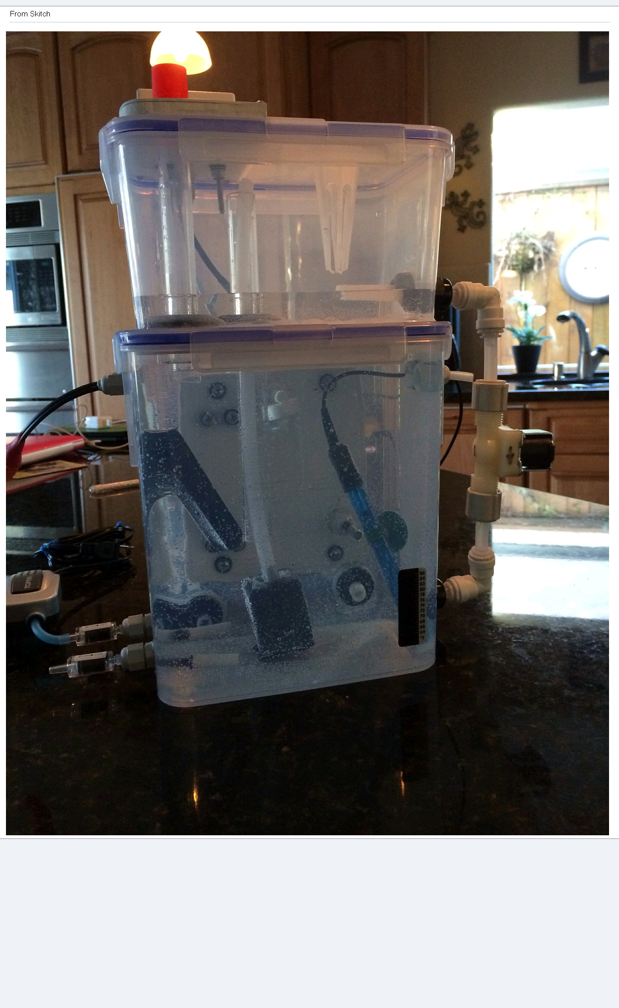 After much thinking about how I could improve the desktop aquaponic automation simulator called agponic-MD (micro-device) I built a new one. It helps to have people that wanted to purchase a few of them. So I got busy and made it a bit larger with expansion capability for future components like a 12V backup system and additional sensors to learn how to automate. Here is the feature set for the re-designed agponic-MD.
Fully valved for water movement and control
Large grow bed and tank configuration
4 – water level control sensors
1 – RH and temp internal probe
3 – temp probes (grow bed / water tank / outside)
1 – water flow sensor
1 – pH probe and connectors
1 – DO or additional probe expansion options for future growth of unit
1 – controllable drain port
1 – grow bed media package to fit grow bed (comes from an established grow bed – so bacteria included)
1 – Container of starter water from an active system ( should you like to cycle the system)
1 – outside tank temp indicator
1 – Heater for tank water
1 – Air pump and stone
Over flow configuration to prevent spillage in grow bed

THINGS IN COMMON — 3D Printing and Aquaponics January 28, 2013
Posted by rik94566 in aquaponics, DIY aquaponics, Rj45 connector, Uncategorized.Tags: aquaponic automation, CAT 5 cable, microcontroller, rik kretzinger
add a comment
Well as it turns out 3D printing and aquaponics do have something in common.
They both need to be water -tight!

Now that I have a Sketch-up model I wanted to get it printed.
I figured out that I have basically 3 options to get this done.
Option One –Buy a 3D printer. I did some research on this and know what I want am ready to go, until I ran the idea by my wife! The unit I wanted costs in the $700.00 range. As on all my projects and ventures my wife has final say so on all things financial. This one did not get approved. Not to say that it won’t happen in the future, but just not right now.
Option Two – Use one of the current leaders in the on-line printing services business. The two leaders that I know of are Shapeways and Ponoko. The other choice here is to go to a TechShop and have them print my model for me.
Option Three – Find someone with a 3d printer and have them make a print for me. I would of course pay them for this service.
Well option one is a no go situation for the present time. Option three will not work, as I do not know anyone well enough to inquire about having them make a print for me.
So Option Two it is.
The TechShop choice is much harder for me as I would have to show up at one of their locations in the bay area with file in hand and then get all signed in to talk with someone about how the whole process works within their structure. Way to much work for a little part.
So I went with Shapways and Ponoko. I signed up and was ready to go, almost…. Well as in all things technical there is a file incompatibility problem with using Sketch-Up and 3D printing together. I now needed to convert my model to a .STL format. I did my research and got a free version of a product that claimed the conversion was easy to do. I did the conversion and loaded my model up to be priced and approved.
Well again I hit an issue. As it happens my model is not “Water-tight” and has to many holes and the model is to small to print on either of the services. I could see no holes in my model and did not understand how to fix this problem. As in all things internet I started on my quest to accomplish my goal of getting a model printed. Now I found myself researching and learning how to make a model water-tight. It is a fun adventure and learned a lot that will be very useful in future designs with Sketch-up
RJ-45 Jack insert development using Sketch-Up January 12, 2013
Posted by rik94566 in aquaponic automation, aquaponics, arduino, DIY aquaponics, Rj45 connector.Tags: aquaponic automation, CAT 5 cable, DIY aquaponics, rik kretzinger
add a comment
Being that I have gone with RJ-45 jacks as a standard for all my aquaponics systems I need a way to connect everything together. The problem I was having is that all the jack insert plates are standard switch plate or phone jack block mounting units and hard to fit into some automation designs. So I built a prototype of what I wanted out of materials I had laying around my shop. It is very rough and not the finished product I was looking for.

RJ-45 Jack head on arduino case
This prototype gave me a good idea of what I needed to make this work and is a good starting platform for future cases to work with my systems that I have on the drawing board. I had been looking for a project to help me learn Sketch-Up. Sketch-up is a 3-D drawing program to do design work with and allows models developed to be printed on 3-D printers. So here I go to make this happen. I am not going to go into all the steps needed on how to install or use Sketch-Up here (you will need to figure this out on your own).
So the most basic element of the project is the individual RJ-45 insert jack. Next step was to get a visual of what this would look like in the real world. I need to visualize my projects before I can build them. The first step was to figure out how I could get a handle on a working model. I started with a single RJ-45 switch plate and moved forward from there. All of this I purchased at Home Depot.
A Starting Point for visual model
This now gave me a working model that I could pull measurements from. This proved to be harder than I thought and has taken me well over 6 months to get working. I have had many starts and stops when I have hit learning curve deficits. In other words me lacking the Sketch-Up skills to pull this project off. I have done a lot of work with VISIO in the past. But, when you jump from a 2-D drawing tools to 3-D drawing programs the learning curve is steep and well worth the effort as you will see in future posts. At least I think so.

Cut away view of the jack insert socket

Visual of the size I am working with for this model
ERROR CAPTURE — why is it important September 13, 2011
Posted by rik94566 in aquaponic automation, aquaponics, arduino, CEA, Controlled Environment Agriculture, DIY aquaponics, DS18B20, indoor aquaponics, indoor gardens, indoor growing, One-wire, sensor, Sensor Hub, Stainless Steel Temp Probe, Standards, Temperature Probe.Tags: aquaponic automation, aquaponic crop, aquaponics, arduino, arduino sketch, automation, CAT 5 cable, CEA, Controlled Environment Agriculture, DIY aquaponics, DS18B20, electronics, indoor aquaponics, microcontroller, rik kretzinger, sensor, Temp Probe, Temperature Probe
add a comment
ERROR CAPTURE – is important so you know if there is a problem with any one of your probes. Good software lets you know that something is not working and where to find the problem. I worked to add this functionality to my sketch, but I am not a good enough programer to figure out where to insert it without causing errors to occur. So I had to drop the feature. Now that I am having to go a new and different direction I will make sure to have ” error capture ” feature in the new sketch configuration.

All probes report same temp
I was using a 2 probe sketch and only had DEVICE O – PROBE-OO7 working , but the temp reported out for DEVICE I – PROBE-OO8 the same temp as Device O. The correct way would be for the sketch to report back that “DEVICE I – PROBE-OO8 not working correctly” this would be ideal. This is really important when you are running a lot of probes.
Load them up — 5 (DS18B20) Temp Probes — SKETCH CRASHES September 10, 2011
Posted by rik94566 in aquaponic automation, aquaponics, arduino, CAT 5 Cable, CEA, Controlled Environment Agriculture, Crop, DIY aquaponics, DS18B20, indoor aquaponics, indoor gardens, indoor growing, Sensor Hub, Stainless Steel Temp Probe, Temperature Probe.Tags: aquaponic automation, aquaponics, arduino, arduino sketch, automation, CAT 5 cable, DIY aquaponics, DS18B20, indoor aquaponics, indoors aquaponics, microcontroller, Miles Burton, rik kretzinger, sensor, Temp Probe, Temperature Probe
2 comments
Well I got it together now and fired everything up — and the sketch crashed… Here are the details of what it looked like.

5 probes and connection through harness
I put the 5 probe sketch I was using up on google docs and made it available at this link:
If you have a problem with the sketch just email me at rik94566@gmail.com and I will send the sketch to you.
Here is what it looks like as it was coded:

5 probe sketch as it ran
Here is the result when I ran the sketch:

Sketch only went this far
Interesting thing is that I worked my way up from 1 probe to 5 probes. Before I started I checked all slots on the harness to make sure there would be no problems with the connections. Everything worked fine through 4 probes. Here is what it looked like running 4 probes.
Now the fun begins.. get to figure out why this does not work with 5 probes. Found out some other things about deviceIndex while I was loading up all the probes. Will blog about that next and present concepts that help drive the One-wire protocols.
SUGRU — makes a harness possible August 21, 2011
Posted by rik94566 in aquaponic automation, aquaponics, arduino, CAT 5 Cable, CEA, DIY aquaponics, DS18B20, Hacks, indoor aquaponics, indoor gardens, indoor growing, Rj45 connector, sensor, Sensor Hub, Stainless Steel Temp Probe, Standards, SUGRU, Temperature Probe.Tags: aquaponic automation, aquaponics, arduino, arduino sketch, automation, CAT 5 cable, CEA, Controlled Environment Agriculture, DIY aquaponics, DS18B20, electronics, hacks, indoor aquaponics, microcontroller, rik kretzinger, sensor, sugru, Temp Probe, Temperature Probe
add a comment
In order to connect up 5 DS18B20 temp probes and make sure all the wires and connectors work correctly took some effort. The fact that a pull-up resistor is required to take readings was an issue for me. I have been using 1/4 watt resistors and in tight spaces my resistor wires kept breaking off. So I needed a way to connect it all up and be protected. Sugru saved the day.

Sugru made a strong bond
I showed you the end product as that is what most people are interested in. But it is important to understand how the end product was created.
Here is the starting point:

pull-up resistor configuration
Spacing of the wires and resistor is a big issue here, as if the spacing is off the connectors will not fit into the holders correctly.

one connection made
Next trick was to get 5 connections completed.

5 connections made

bend it just right to get correct spacing

side view

Front view

end product
Now it is possible to continue testing my DS18B20 temp probes with more than 2 probes. This creation will allow me to build a temp probe hub using Cat 5 cable and RJ45 connectors. This harness will also make it possible to stay with my basic premise of being able to replace any component in my systems with in 5 minutes.
NEXT GOAL — Temp probe Hub (DS18B20 & RJ45) August 12, 2011
Posted by rik94566 in aquaponic automation, aquaponics, arduino, CAT 5 Cable, CEA, Controlled Environment Agriculture, DIY aquaponics, DS18B20, indoor aquaponics, indoor growing, Instructables, Rj45 connector, Stainless Steel Temp Probe, Temperature Probe.Tags: aquaponic automation, aquaponics, arduino sketch, CAT 5 cable, CEA, Controlled Environment Agriculture, DIY aquaponics, DS18B20, electronics, hacks, indoor aquaponics, indoors aquaponics, microcontroller, rik kretzinger, sensor, Temp Probe, Temperature Probe
4 comments

5 buttons and 5 temp readings
Here we go…. The goal here is to create a DS18B20 hub using RJ45 connections and have results displayed on a computer screen or LCD. I want to achieve the functionality of a PINPOINT Temp unit I am currently using. You can check it out here:
This unit allows you to see individual readings from each one of the probes you have connected and you also have the option to rotate through all the probes and see their values. The Pinpoint unit is limited to 4 probes and I know it is wireless, but that will come later. It is totally possible with arduinos and the things we are learning here.
When I get my hub working it will hold 5 probes and the analog button panel will display the correct temperature for the button pushed. Button 1 gives reading from probe 1 and so on. If all goes well, I will be able to hold down button 1 for about 3 seconds and then all temp probes values will be displayed in order starting with the first temp probe.
MANY THINGS TO WORK OUT:
- Sketch for analog button panel.
- Reading individual temp probe values using HEX code.
- Determine the resistor values needed when working with 5 probes. ( did a lot of research on this one)
- Will I need external power supply.
- Figure out how to connect my power wires and signal wires with the correct resistor and be strong enough to hold up to being bent without breaking the resistor wires ends.
If all goes well I will be able to create an Instructable so others can build their own DS18B20 hub and use them in any location that people want to track and drive control of enviroments with tempeture results.
So stay tuned it should be a fun and exciting fall….
Reading Two Temp Probes — DS18B20 June 14, 2011
Posted by rik94566 in aquaponic automation, aquaponics, arduino, CAT 5 Cable, DIY aquaponics, DS18B20, Hacks, indoor aquaponics, indoor gardens, indoor growing, Rj45 connector, sensor, Sensor Hub, Stainless Steel Temp Probe, Standards, Temperature Probe.Tags: aquaponic automation, aquaponics, arduino, arduino sketch, automation, CAT 5 cable, DIY aquaponics, DS18B20, electronics, hacks, indoor aquaponics, indoors aquaponics, microcontroller, Miles Burton, rik kretzinger, Temp Probe, Temperature Probe
2 comments
Reading two (2) DS18B20 Temperature Probes requires an added level of complexity. You need to have a sketch that will accommodate the addition Temp Probe and report out the readings. You need to be able to tell each Temp Probe apart and know which probe is being read and when. Using the RJ45 2 jack hub I constructed I added the 4.7K ohm resistors and wired up both sides of the hub. This is the same as the 3-wire configuration test and talked about in prior blog discussions.

Hub wired up for testing
Here is what the connections look like on the arduino side of the test.

Arduino connections for 2 Temperature Probes
Next I need to build out the arduino sketch that I have been using for testing of all my connections. Miles Burton talks about this in the code he supplies on his wiki regarding “Dallas Temperature Control Library”. It can be found here:
http://www.milesburton.com/?title=Dallas_Temperature_Control_Library
Knowing this I went to work to creating a sketch that could read 2 probes. So here is what I came up with.
/*
Testing Sketch to test 2 temp probes using DS18B20 IC for Stainless Steel probes.
Sketch was created by Miles Burton and changed to
display both C and F temperatures and 2 devices using the serial
monitor for display.
created on 06/01/11
by rik kretzinger version 2.1
*/
#include <OneWire.h>
#include <DallasTemperature.h>
// Data wire is plugged into pin 8 on the Arduino
#define ONE_WIRE_BUS 8
// Setup a oneWire instance to communicate with any OneWire
// devices (not just Maxim/Dallas temperature ICs)
OneWire oneWire(ONE_WIRE_BUS);
// Pass our oneWire reference to Dallas Temperature.
DallasTemperature sensors(&oneWire);
void setup(void)
{
// start serial port
Serial.begin(9600);
Serial.println(“Dallas Temperature IC Control Library Demo”);
// Start up the library
sensors.begin();
}
void loop(void)
{
// call sensors.requestTemperatures() to issue a global temperature
// request to all devices on the bus
Serial.print(“Requesting temperatures…”);
delay(1000);
sensors.requestTemperatures(); // Send the command to get temperatures
Serial.println(“DONE”);
delay(1000);
Serial.print(“111111111111111111111111111111111111111111111111”);
Serial.println();
Serial.print(“Temperature for Probe 002 is: “);
Serial.print(sensors.getTempCByIndex(0)); // Why “byIndex”? You can have more
// than one IC on the same bus.
// 0 refers to the first IC on the wire.
Serial.println(” C”);
Serial.print(“FAHRENHEIT CONVERSION “);
Serial.print(((sensors.getTempCByIndex(0)*1.8)+32)); // test this line
Serial.println(” F”);
Serial.println();
Serial.print(“22222222222222222222222222222222222222222222222”);
Serial.println();
Serial.print(“Temperature for Probe 003 is: “);
Serial.print(sensors.getTempCByIndex(1)); // Why “byIndex”? You can have more
// than one IC on the same bus.
// 0 refers to the first IC on the wire.
Serial.println(” C”);
Serial.print(“FAHRENHEIT CONVERSION “);
Serial.print(((sensors.getTempCByIndex(1)*1.8)+32)); // test this line
Serial.println(” F”);
Serial.println();
Serial.println();
Serial.print(“END OF TEMP PRBOE READINGS THIS CYCLE”);
Serial.println();
}
I have my probes indexed as P002 and P003. Knowing this the sketch calls out device (0) first probe (P_002) read and device (1) being the second device (P_003) being read. So you need to know which is which. This is because the library starts the device at “0” and build up from there, so the next one read will be “1”, the next one is “2” and so on. I think you get the idea.
Here are my results from running the above sketch:

2 - Temp Probe readings
10,000 views surpassed on Instructables June 11, 2011
Posted by rik94566 in aquaponic automation, aquaponics, arduino, CAT 5 Cable, Crop, DIY aquaponics, DS18B20, Float Sensor, Float Switch, general, Glow Panel 45, Gravity feed valves, Hacks, indoor aquaponics, indoor gardens, indoor growing, Instructables, LED growing, LED lights, plumbing, POW-Rduino, Rj45 connector, sensor, Sensor Hub, Stainless Steel Temp Probe, Standards, sunshine systems, Suppliers, Temperature Probe, Yield Results.Tags: aquaponic automation, aquaponics, arduino, arduino sketch, CAT 5 cable, DIY aquaponics, DS18B20, electronics, float sensor, hacks, indoor aquaponics, indoors aquaponics, microcontroller, rik kretzinger, sensor, Temp Probe, Temperature Probe
1 comment so far
I have written 3 instructables over the last 2 years. I have just gone over 10,000 views. Never thought I would every have had that many views with only 3 instructions. Always good to know people are interested in what I am interested in.

Passed 10,000 views
SUGRU – fills in the holes June 7, 2011
Posted by rik94566 in aquaponic automation, aquaponics, CAT 5 Cable, DIY aquaponics, DS18B20, Float Sensor, Float Switch, Hacks, Home Depot, indoor aquaponics, indoor gardens, indoor growing, Rj45 connector, sensor, Sensor Hub, Stainless Steel Temp Probe, Standards, SUGRU, Suppliers, Temperature Probe.Tags: aquaponic automation, aquaponics, arduino, automation, CAT 5 cable, DIY aquaponics, DS18B20, electronics, float sensor, float switch, hacks, indoor aquaponics, indoors aquaponics, microcontroller, rik kretzinger, sensor, Temp Probe, Temperature Probe
1 comment so far
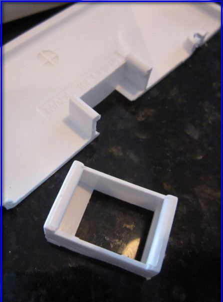
Now that I have working Sensors on a standardized connection platform (CAT 5 & RJ45). I need to figure out how to use off the shelf housings that will be plug-n-play for my aquaponic units. The problem is that nothing is water resistant and they all have lots of openings. That is because most if not all are for indoor use. All the outdoor options are to large for my applications. So I went with a standard indoor 2-Port QuickPort I purchased at Home Depot.

Leviton 2-Port Surface Mount Housing
With a little help from SUGRU I was able to fill in the holes and can now mount the completed unit on my aquatubes. This will allow me to cover all my sensor connections and transition over to RJ45 connectors.
Here is what I started with:

Starting Housing
Here is what it looked like before assembly:

Openings filled before assembly - Inside look

Bottom View
Here is the completed assembly:

Back View of Completed Assembly

Front View of Completed Assembly
How the openings match-up:

Opening that match-up
Now I am ready to connect up the sensors and mount the completed assembly on the aquatubes hook-up my CAT 5 and I am ready to sense all inputs. O yes, I need some White SUGRU to make it look better. I am placing my order today!
