THE WAY FORWARD — use of HEX code for DS18B20 October 6, 2011
Posted by rik94566 in 1-wire, aquaponic automation, aquaponics, arduino, Arduino Your Environment, Controlled Environment Agriculture, DIY aquaponics, DS18B20, indoor aquaponics, indoor gardens, indoor growing, Links, One-wire, Temperature Probe.Tags: aquaponic automation, aquaponic crop, aquaponics, arduino, arduino sketch, automation, CEA, Controlled Environment Agriculture, DIY aquaponics, DS18B20, electronics, indoor aquaponics, indoors aquaponics, microcontroller, Miles Burton, rik kretzinger, sensor, Temp Probe, Temperature Probe
3 comments
It became clear to me that the path I was on was leading me to a deadend when it comes to using a large number of DS18B20 probes. The sketches I was working with had problems for me. A number of comments and suggestions from readers along with research on my part I have figured out that the use of HEX code is the way to go. This new direction will get me to the end now. This seems to be the most traveled path when it comes to the DS18B20 platform. The best work I can find going this direction comes from two main sites. The first site Hacktronics.com has some very good tutorials on this subject. The second site is a spin off of the Hacktronics site in that the same code is used, but changed to be output to a LCD display (very useful stuff). These two sites will be very useful for me going forward and will enable me to finish-up on the Temp probe side of things and will allow me to move on to the others sensors I have been working with.
The first is:
http://www.hacktronics.com/Tutorials/arduino-1-wire-tutorial.html
Second site:
RESISTORS — and use with DS18B20 September 17, 2011
Posted by rik94566 in 1-wire, aquaponic automation, aquaponics, arduino, CAT 5 Cable, DIY aquaponics, DS18B20, indoor aquaponics, indoor gardens, indoor growing, One-wire, sensor, Sensor Hub, Stainless Steel Temp Probe, Temperature Probe.Tags: aquaponic automation, aquaponic crop, aquaponics, arduino, arduino sketch, automation, CEA, Controlled Environment Agriculture, DIY aquaponics, DS18B20, indoor aquaponics, microcontroller, Miles Burton, rik kretzinger, sensor, Temp Probe, Temperature Probe
3 comments
In order to read DS18B20 IC’s or temperature probes a resistor is required. The standard one used in almost all work done on breadboard examples are 4.7K ohm. Upon researching work done with 1-wire temp sensing most people are only working with 1 to 2 DS18B20’s and most of this is with breadboards. In a few cases people are using 3 or 4 only. I have found no cases where anyone is working and in production with 5 or more DS18B20 probes. So I think this is somewhat new ground. That being the case, there is a lot written that as you increase the number of DS18B20’s the power draw becomes greater and you need to decrease the resistor size. The common thought is to go to 2.2K ohm resistor. If that does not work the next size to work with is 1.0K ohm. Well this will be my next testing platform. I will be testing both the 4.7K and 2.2K resistors with up to 10 DS18B20 probes to determine what works and what does not work. Along the way I will determine what happens and how it happens and where the breaking points are in the hardware and the sketches. Will be fun stuff.
Load them up — 5 (DS18B20) Temp Probes — SKETCH CRASHES September 10, 2011
Posted by rik94566 in aquaponic automation, aquaponics, arduino, CAT 5 Cable, CEA, Controlled Environment Agriculture, Crop, DIY aquaponics, DS18B20, indoor aquaponics, indoor gardens, indoor growing, Sensor Hub, Stainless Steel Temp Probe, Temperature Probe.Tags: aquaponic automation, aquaponics, arduino, arduino sketch, automation, CAT 5 cable, DIY aquaponics, DS18B20, indoor aquaponics, indoors aquaponics, microcontroller, Miles Burton, rik kretzinger, sensor, Temp Probe, Temperature Probe
2 comments
Well I got it together now and fired everything up — and the sketch crashed… Here are the details of what it looked like.
I put the 5 probe sketch I was using up on google docs and made it available at this link:
If you have a problem with the sketch just email me at rik94566@gmail.com and I will send the sketch to you.
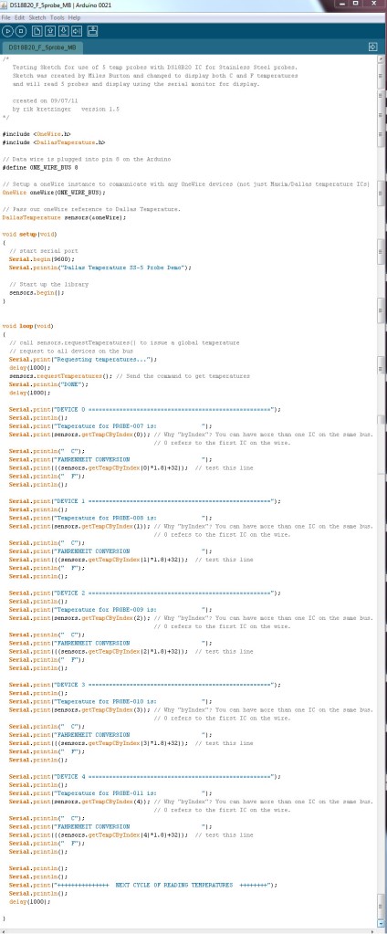
Here is what it looks like as it was coded:
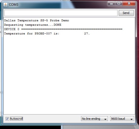
Here is the result when I ran the sketch:
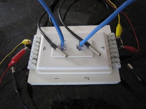
Interesting thing is that I worked my way up from 1 probe to 5 probes. Before I started I checked all slots on the harness to make sure there would be no problems with the connections. Everything worked fine through 4 probes. Here is what it looked like running 4 probes.
Now the fun begins.. get to figure out why this does not work with 5 probes. Found out some other things about deviceIndex while I was loading up all the probes. Will blog about that next and present concepts that help drive the One-wire protocols.
Reading Two Temp Probes — DS18B20 June 14, 2011
Posted by rik94566 in aquaponic automation, aquaponics, arduino, CAT 5 Cable, DIY aquaponics, DS18B20, Hacks, indoor aquaponics, indoor gardens, indoor growing, Rj45 connector, sensor, Sensor Hub, Stainless Steel Temp Probe, Standards, Temperature Probe.Tags: aquaponic automation, aquaponics, arduino, arduino sketch, automation, CAT 5 cable, DIY aquaponics, DS18B20, electronics, hacks, indoor aquaponics, indoors aquaponics, microcontroller, Miles Burton, rik kretzinger, Temp Probe, Temperature Probe
2 comments
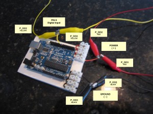
Reading two (2) DS18B20 Temperature Probes requires an added level of complexity. You need to have a sketch that will accommodate the addition Temp Probe and report out the readings. You need to be able to tell each Temp Probe apart and know which probe is being read and when. Using the RJ45 2 jack hub I constructed I added the 4.7K ohm resistors and wired up both sides of the hub. This is the same as the 3-wire configuration test and talked about in prior blog discussions.
Here is what the connections look like on the arduino side of the test.
Next I need to build out the arduino sketch that I have been using for testing of all my connections. Miles Burton talks about this in the code he supplies on his wiki regarding “Dallas Temperature Control Library”. It can be found here:
http://www.milesburton.com/?title=Dallas_Temperature_Control_Library
Knowing this I went to work to creating a sketch that could read 2 probes. So here is what I came up with.
/*
Testing Sketch to test 2 temp probes using DS18B20 IC for Stainless Steel probes.
Sketch was created by Miles Burton and changed to
display both C and F temperatures and 2 devices using the serial
monitor for display.
created on 06/01/11
by rik kretzinger version 2.1
*/
#include <OneWire.h>
#include <DallasTemperature.h>
// Data wire is plugged into pin 8 on the Arduino
#define ONE_WIRE_BUS 8
// Setup a oneWire instance to communicate with any OneWire
// devices (not just Maxim/Dallas temperature ICs)
OneWire oneWire(ONE_WIRE_BUS);
// Pass our oneWire reference to Dallas Temperature.
DallasTemperature sensors(&oneWire);
void setup(void)
{
// start serial port
Serial.begin(9600);
Serial.println(“Dallas Temperature IC Control Library Demo”);
// Start up the library
sensors.begin();
}
void loop(void)
{
// call sensors.requestTemperatures() to issue a global temperature
// request to all devices on the bus
Serial.print(“Requesting temperatures…”);
delay(1000);
sensors.requestTemperatures(); // Send the command to get temperatures
Serial.println(“DONE”);
delay(1000);
Serial.print(“111111111111111111111111111111111111111111111111”);
Serial.println();
Serial.print(“Temperature for Probe 002 is: “);
Serial.print(sensors.getTempCByIndex(0)); // Why “byIndex”? You can have more
// than one IC on the same bus.
// 0 refers to the first IC on the wire.
Serial.println(” C”);
Serial.print(“FAHRENHEIT CONVERSION “);
Serial.print(((sensors.getTempCByIndex(0)*1.8)+32)); // test this line
Serial.println(” F”);
Serial.println();
Serial.print(“22222222222222222222222222222222222222222222222”);
Serial.println();
Serial.print(“Temperature for Probe 003 is: “);
Serial.print(sensors.getTempCByIndex(1)); // Why “byIndex”? You can have more
// than one IC on the same bus.
// 0 refers to the first IC on the wire.
Serial.println(” C”);
Serial.print(“FAHRENHEIT CONVERSION “);
Serial.print(((sensors.getTempCByIndex(1)*1.8)+32)); // test this line
Serial.println(” F”);
Serial.println();
Serial.println();
Serial.print(“END OF TEMP PRBOE READINGS THIS CYCLE”);
Serial.println();
}
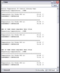
I have my probes indexed as P002 and P003. Knowing this the sketch calls out device (0) first probe (P_002) read and device (1) being the second device (P_003) being read. So you need to know which is which. This is because the library starts the device at “0” and build up from there, so the next one read will be “1”, the next one is “2” and so on. I think you get the idea.
Here are my results from running the above sketch:
Instructable Published on work done on the DS18B20 June 1, 2011
Posted by rik94566 in aquaponic automation, aquaponics, arduino, CAT 5 Cable, DIY aquaponics, DS18B20, Home Depot, indoor aquaponics, indoor gardens, indoor growing, Instructables, Lowes, Rj45 connector, sensor, Stainless Steel Temp Probe, Standards, Suppliers, Temperature Probe.Tags: aquaponic automation, aquaponics, arduino, arduino sketch, automation, CAT 5 cable, DIY aquaponics, DS18B20, electronics, hacks, indoor aquaponics, indoors aquaponics, microcontroller, Miles Burton, rik kretzinger, sensor, Temp Probe, Temperature Probe
1 comment so far
Tonight I pulled all the posts from my work on the DS18B20 assembly and put it into an Instructable for anyone interested. I will see how how many views it will generate.
Temp Probe (DS18B20) – results without pull-up resistor May 8, 2011
Posted by rik94566 in aquaponic automation, aquaponics, arduino, DIY aquaponics, DS18B20, indoor gardens, indoor growing, Stainless Steel Temp Probe, Temperature Probe.Tags: aquaponic automation, aquaponics, arduino, arduino sketch, automation, DIY aquaponics, DS18B20, electronics, indoors aquaponics, microcontroller, Miles Burton, rik kretzinger, sensor, Temp Probe, Temperature Probe
2 comments
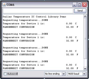
Here are the results that are returned from my testing code of probes. I now know what reading I will get if the 4.7K ohm pull-up resistor is not present or connected wrong or a connection has broken. I have provided the sketch for download or you can copy it from below.
SKETCH – TO TEST PROBES
/*
Testing Sketch to test construction of temp probes using DS18B20 IC for Stainless Steel probes.
Sketch was created by Miles Burton and changed to display both C and F temperatures using the serial
monitor for display.
created on 11/20/10
by rik kretzinger version 1.3
*/
#include <OneWire.h>
#include <DallasTemperature.h>
// Data wire is plugged into pin 8 on the Arduino
#define ONE_WIRE_BUS 8
// Setup a oneWire instance to communicate with any OneWire devices (not just Maxim/Dallas temperature ICs)
OneWire oneWire(ONE_WIRE_BUS);
// Pass our oneWire reference to Dallas Temperature.
DallasTemperature sensors(&oneWire);
void setup(void)
{
// start serial port
Serial.begin(9600);
Serial.println(“Dallas Temperature IC Control Library Demo”);
// Start up the library
sensors.begin();
}
void loop(void)
{
// call sensors.requestTemperatures() to issue a global temperature
// request to all devices on the bus
Serial.print(“Requesting temperatures…”);
delay(1000);
sensors.requestTemperatures(); // Send the command to get temperatures
Serial.println(“DONE”);
delay(1000);
Serial.print(“Temperature for Device 1 is: “);
Serial.print(sensors.getTempCByIndex(0)); // Why “byIndex”? You can have more than one IC on the same bus.
// 0 refers to the first IC on the wire.
Serial.println(” C”);
Serial.print(“FAHRENHEIT CONVERSION “);
Serial.print(((sensors.getTempCByIndex(0)*1.8)+32)); // test this line
Serial.println(” F”);
Serial.println();
}
DOWNLOAD HERE:
